 Models: 2001-’04 Ford Escape
Some vehicles may exhibit a powertrain control module (PCM) concern that results in no crank, no start or malfunction indicator lamp (MIL) with one or more diagnostic trouble codes (DTCs) present.
There may also be intermittent or inoperative power windows, door locks, keyless entry system, lighting, speed control, radio, instrument cluster warning lamps (possibly dimly illuminated instead of being off) or other electrical accessories.
The concern is typically more noticeable in wet and/or cold weather conditions.
This may be the result of connector terminal corrosion in C134, C263 or the central junction box (CJB), which results in either high resistance between the male and female terminals or a short between two or more circuits due to bridging through any corrosion that may be present.
Corrosion in C134 may be the result of improper positioning/sealing of C134. Corrosion in C263 or the CJB may be due to a water leak in the left hand A-pillar area.
Follow the Service Procedure to inspect and repair the connector terminals for evidence of corrosion. Repair any sources of water entry. If no signs of corrosion or water entry are found, follow normal diagnostics.
 Service Procedure
Note: When diagnosing the cause of a PCM failure, it is critical that this inspection and repair procedure be completed in its entirety before installing a replacement service part.
The possibility exists for a 12-volt short to the 5-volt VREF (circuit). Installation of a service replacement PCM without eliminating the 12-volt short will result in repeat PCM failure.
Inspect and repair the following connectors:
C134
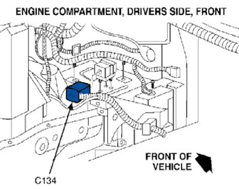
1. Open the hood and locate C134 (Figure 1).
2. Disconnect the connector halves and thoroughly inspect the terminals. Clean any corrosion that may be present and replace any damaged terminals.
3. Use shop air to blow out any moisture that may be present in the terminals, then apply dielectric grease to the terminals in both halves of the connector.
4. Reconnect the connector halves and close the hood.
C263
1. Open the driver’s door and remove the lower kick panel.
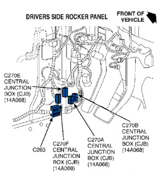
2. Locate C263 as shown in Figure 2.
3. Disconnect the connector halves.
4. Pry out the terminal retainer and thoroughly inspect the terminals.
Note: The corrosion will not be visible unless the terminal retainer is removed.
5. Clean any corrosion that may be present and replace any damaged terminals.
6. Work dielectric grease into the side opening in the connector, then reinstall the terminal retainer.
7. Apply dielectric grease to the terminals in both halves of the connector.
8. Reconnect the connector halves.
CJB (Central Junction Box)
1. Locate the CJB (Figure 2).
2. Disconnect the four harness connectors from the front and the two connectors from the rear of the CJB, and remove the CJB.
3. Inspect the terminals and also the back side of the CJB for evidence of water damage or corrosion.
4. Clean any corrosion that may be present and replace any damaged terminals or components.
5. Apply dielectric grease to the terminals in the harness connectors.
6. Reconnect the six harness connectors and reinstall the CJB.
7. Reinstall the lower kick panel.
Note: If any corrosion was found in either C263 or the CJB, the source of the water entry must be identified to prevent a repeat repair.
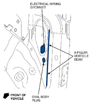
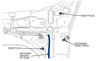
Follow standard water testing procedures to identify the source of any leaks.
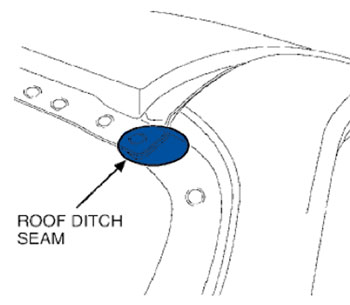
Figures 3 through 5 identify some common sources of water leaks.
Courtesy of Mitchell 1.


