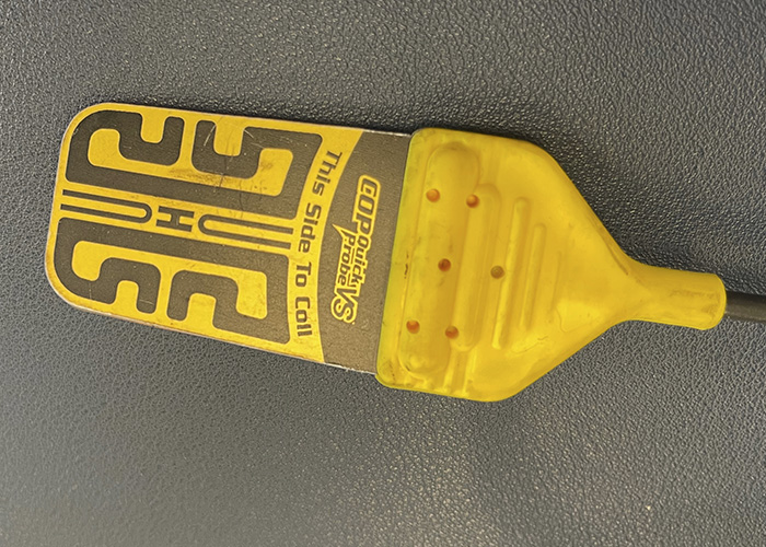
A secondary ignition waveform is not just about the coil; it is also about the resistance of the air and fuel mixture inside the combustion chamber. When you are looking at a secondary ignition waveform, you need to be looking at the spikes and the hash in between. Measuring the voltage of the secondary ignition directly is not an option. The high voltages will damage any scope or meter. Capturing a secondary ignition waveform requires a capacitive probe. This type of probe can be either the traditional clamp over an ignition wire or a “paddle” that makes contact with the surface of the coil or wire.
Most clamp or paddle probes have a conversion factor of 10:1. This means that one volt at the scope input equals 1,000 volts or one kilovolt (kV) in the secondary. Some clamps or probes may have an attenuator (10:1 or 20:1); some scopes will convert the voltage scale to kV when the ignition probe is selected.
What are the Settings for the Scope?
When you are trying to set up a scope to measure secondary ignition waveforms, the goal is to capture the ignition event from when power is applied to the coil to the point where the coil oscillates with the remaining energy. This can happen in 6-10 milliseconds. One millisecond per division is typically the optimal time base, depending on the size of your screen and the type of ignition system.
A healthy coil and ignition system generates 3-4 kV at idle. As load and engine speed increase, the kV spike will increase. Some systems can create more than 50 kV under certain conditions. You may need to adjust your voltage scales to capture the total output of the spike.
On most scopes, the trigger should be set to auto or single with an increasing slope. With some scopes, you will be able to use an auto or repeat trigger setting to stabilize the waveform. There are also options to offset or delay the trigger to fit the entire event on one screen. If you have a more advanced scope, you can select the secondary ignition probe in the probes menu, and the presets will load the correct voltage range, time base and type of trigger.
What are the Sections of the Waveform?
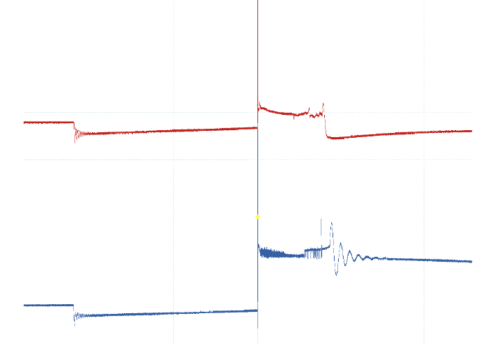
A secondary ignition waveform can be broken down into three parts. First, the area of the waveform that shows dwell where the secondary of the coil is saturated with energy from the primary. Second, the spike shows the initial start of the spark between the electrodes. Third, the burn time is the area of the wave where the spark is burning between the electrodes and eventually stops.
Saturation/Dwell
The first part of the waveform is the charging of the secondary coil by the primary. This is where the energy of the primary saturates the secondary coil. There will be an initial sharp voltage drop followed by a sine wave, which is a coil oscillation. This oscillation is the module turning on power to the coil. As the secondary becomes saturated, the line will slowly go up in a steady ramp. The critical shape of this part of the waveform should be a smooth ramp upward. It can change due to demands on the engine.
Spike
The spike is where the coil discharges, and the spark jumps from one electrode to the other. This spike changes depending on the resistance between the electrodes. The resistance depends on what is going on inside the combustion chamber.
If the sparkline does not increase when the throttle is snapped or is lower when compared to the other coils, it is a sign the spark might be escaping to areas other than the spark plug electrodes. This could be caused by a shorted connector or boot with an air gap.
The Burn
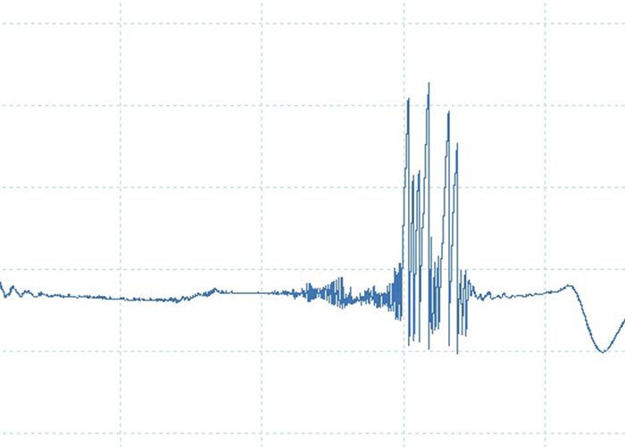
The burn line is the burn time of the spark between the electrodes. It will typically last 2 to 3 milliseconds. The line can have slight changes and can appear jagged on some scopes. This has been theorized as changes in the gases and turbulence in the cylinder.
At the end of the burn line are the coil oscillations. This is the energy left over in the coil. It should have three or four smooth humps. If it has a spike and a short burn time, it is a sign there is an opening in the wire or boot that is preventing the energy from going to the plug.
On modern coil over plug, wasted spark or coil near plug systems, you are using the secondary waveform as a comparative tool. You can compare a waveform to a known-good pattern from a database or you can compare the waveform to the other cylinders. Waveforms will differ from engine to engine.