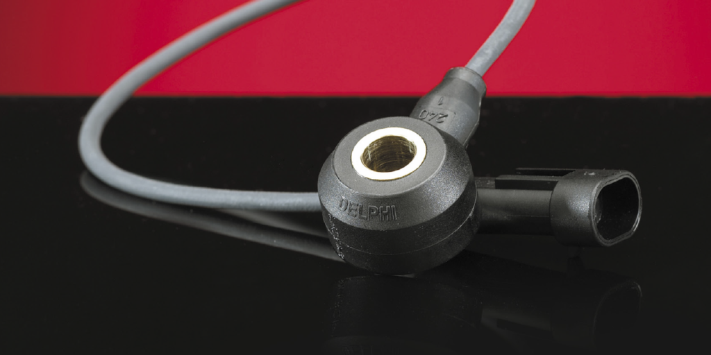
The knock sensor is a piezoelectric accelerometer that acts as a microphone on the engine. It converts vibrations into alternating current (AC) signal. When the crystal inside the sensor is vibrated, it produces an AC voltage. The greater the vibration or shock, the higher the voltage and frequency.
The ECM can look at the output from the knock sensor and determine if something is going wrong in the combustion chamber and take action, like changing the ignition timing or adding fuel.
The knock sensor is not the only sensor responsible for detecting engine knock. The ECM looks at the crank angle sensor data to determine at which cylinder the event is taking place and whether the crankshaft had a sudden change in speed. This way, the ECM can determine if the driver just hit a pothole, or if a knock occurred. It can also identify if the event happened before or after top dead center.
Testing
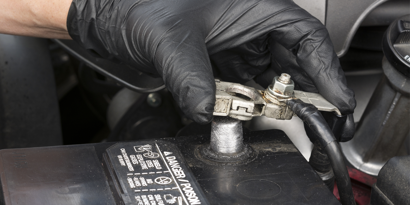
If you’re using a meter, set it to AC volts. If you are using a scope, make sure the AC filtering is turned off. If you are testing the sensor on the vehicle, you need to access the connector. Knock sensors have only two wires.
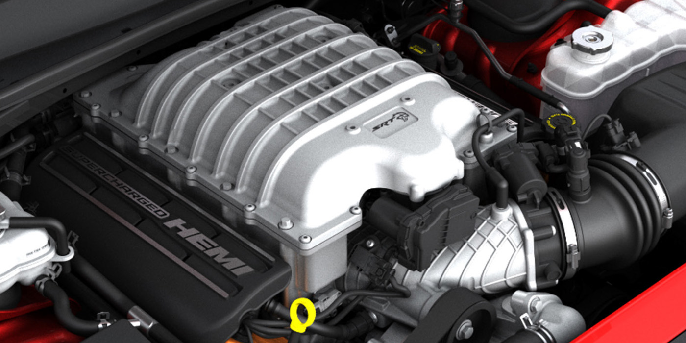
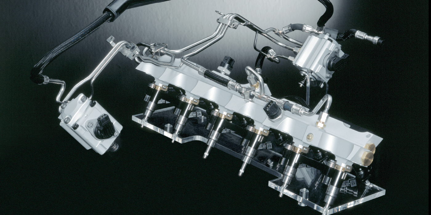
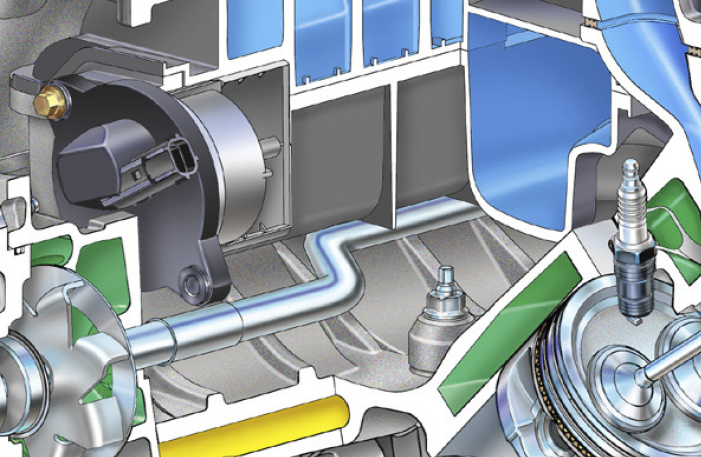
Knock sensors are mounted on the block near the base of the cylinder head. On an inline engine, the sensor is easy to access. On V6 and V8 engines, the knock sensor might be in the valley of the engine under the intake manifold.
There are two schools of thought for testing. If the sensor is out in the open, you can use a blunt chisel and hammer and strike the area around the knock sensor.
If the sensor is inaccessible, you can run the engine and pull the fuse for the fuel pump and let the engine stall. The lean conditions might produce an engine knock. But, this type of testing can be hard on an engine.
Knock sensors rarely degrade; they typically fail and will not produce a signal no matter how hard you hit them. When you are looking at a meter, you will see a change of 0.06V when striking around the sensor. Using the min/max feature, you might see higher voltages. You can also check the amount of resistance across the sensor and verify the value with the service information. A scope can provide you with a better picture of what the sensor is doing, even while the engine is running.
Some engine management systems will send out a brief bias voltage signal to check the condition of the circuit when the vehicle is started. If the circuit has higher-than-normal resistance due to corrosion or a bad connection, the voltage will drop and a code will be set for low voltage. The ECM also knows what types of voltage the knock sensor should produce during startup and idle, and it will set a code if it does not see the correct value.
If a knock sensor-related code is set, the ECM may use a more conservative fuel map or even limit engine loads and RPM. This is to protect the engine and safeguard against possible damage to the combustion chamber.
Misfire Detection
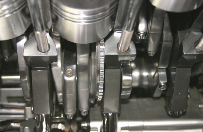
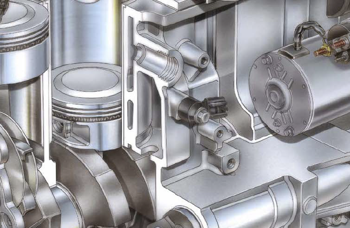
With most engines, the crankshaft position and knock sensors work together to detect a misfire, detonation or pre-ignition. The engine management system calculates the time between the edges of the crank reluctor wheel teeth by receiving a signal from the CKP sensor. The crankshaft rotational velocity and acceleration are compared in the event of a power loss from each cylinder.
When a power loss is less than the calibrated value, the suspected cylinder is determined to be misfiring by the PCM. The misfire detection is enabled after certain base information is received by the PCM. Typically, engine coolant temperature, cylinder head temperature, intake air temperature and, if equipped, the mass air flow sensor (or a combination of these) are used to evaluate the condition as well as the crank and cam positions.
With the sensitivity of these sensors, they can generate a false misfire under certain conditions. For example, driving on a very muddy or dusty road can throw debris into the reluctor teeth (on engines with external reluctor wheels mounted on the crankshaft). Water in the fuel tank can be sent through the injectors and cause a misfire condition or even a lean condition, which can also cause the PCM to see a misfire – usually a random misfire code and not an individually isolated cylinder misfire or verified with the knock sensor.