Ever since the fuel pump was moved to the fuel tank, fuel pressure replaced the float height as a measure of fuel system health and performance. Checking the height of the float might have required some disassembly or special tools to bend the arms of the float.
When the shift was made to port or throttle body fuel injection, all a technician needed to diagnose a fuel problem was a set of “noid lights,” a fuel pressure gauge and maybe a multi-meter. Measuring the fuel pressure typically required checking the pressure at idle and under load. Most of the these tools can’t be used on the high pressure side of a direct-injection system because of higher pressures and changes in the injector location and technology.
Voltages from the injector drivers can range from 30-120 volts depending on the system, and pressures can go as high as 2,300 psi. The go-to tool for direct injection is a scan tool that can look at special direct fuel injection parameters and perform bidirectional tests.
Some of the tests are the same, such as the injector balance and load testing, but more insight is needed into how the placement of the injector and the high-pressure fuel pump play into drivability diagnostics.
PRESSURE DIAGNOSTICS
You will never find a Schrader valve or port to measure pressure on a direct-injection system, even on the low side. If you were able to tap into the low side with an analog gauge, you would see pressures rapidly changing as demands on the engine changed.
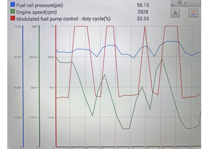
Direct injection pressure is measured with sensors, and the signals are used to determine pump speed and/or volume. So, you’ll need a scan tool to look at the pressures.
Most direct-injection systems use piezoresistive pressure sensors on the low and high side of the fuel system. They typically have three wires going to the sensor. One wire provides the reference voltage that is typically five volts, and the sensing element changes the resistance and turns reference voltage to signal voltage. The third wire is almost always a ground.
The ECM will turn the signal voltage into a calculated pressure that has a ±2% accuracy. Measuring the values with a scope or meter will not yield any important information, so always look at the value with a scan tool.
High-pressure sensors may use a metallic membrane on a resistance bridge. When pressure is applied, the bridge generates a change in resistance that will cause a change in the applied voltage.
The ECM is supposed to ensure the fuel pump is supplying the correct pressure to the high-pressure pump. The ECM will pulse the low-pressure pump so that the correct pressure is generated. The system typically has a regulator and no return lines. Some systems even have integrated temperature sensors in the lines that are used to calculate the density of the fuel so that the fuel trim can be tuned to the amount of energy in the fuel.
LOW-PRESSURE/SUPPLY PUMPS
The low-pressure, in-tank pump is typically controlled by the ECM with a pulse-width modulated voltage signal. Its main responsibility is to provide the correct volume and pressure to the high-pressure pump. With this arrangement, there is no need for a return line.
The supply pump also can activate a limp-home pump if the high-pressure pump fails. If the ECM detects a failure of the high-pressure pump with information from the high-pressure sensor, it will increase the output of the supply pump and the open injector time so that the engine can continue in a restricted power mode.
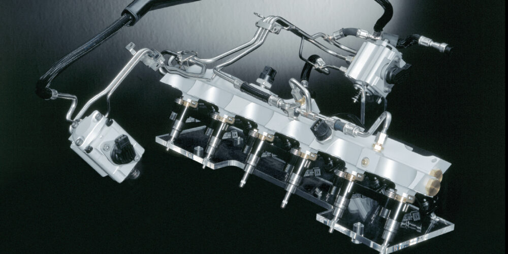
HIGH-PRESSURE PUMPS
A gasoline direct-injected high-pressure fuel pump is what happens if an A/C compressor and ABS HCU had a baby. Like its parents, a high-pressure fuel pump uses a piston to generate pressure. But, the high-pressure fuel pump takes after the A/C compressor in the way it regulates the stroke and volume of fuel being compressed.
Mechanical pumps use pressure and other engine-related information to determine output, which is controlled by an actuator, typically on the intake side of the high-pressure pump. When there is no voltage applied to the solenoid, it will revert to the low-pressure setting.
This pump is precision-machined to generate fuel pressure to the rail up to 5,000 psi on some newer applications. Fuel lubricates the internal parts of the pump, and if the fuel system is dry, the pump can be damaged.
The main destroyer of high-pressure fuel pumps is neglected oil change intervals. Wear between the camshaft lobes and the high-pressure pump prevents the fuel pump from generating enough piston movement. You should always examine the lobes on the camshaft before installing a new (and very expensive) high-pressure fuel pump. A lack-of-power complaint may improve, but it will never be completely corrected.
INJECTORS
With more than 2,000 psi on the backside of an injector, and combustion pressures on the other side, more than 12 volts are needed to pulse the injector. Most direct-injection systems use a capacitor and voltage inverter to create voltages that can range from 40 to 100 volts, depending on the system. It’s possible to view the output of the driver using an induction clamp.
DIAGNOSTIC MARGINS
Engineers are building test cylinders with ruby quartz windows and are using the most sophisticated high-speed cameras in the world to determine the best possible combustion event under different loads. They want to tune the perfect combustion event in which all the fuel is burned and the lowest amount of emissions makes it to the converter.
This quest for perfection will become a diagnostic challenge for technicians in the years to come. As engineers aim to squeeze every bit of energy out of every drop of fuel, all the elements in the system will be operating on the razor’s edge of incurring drivability problems. For example, a little bit of carbon on an intake valve can cause the air going into the combustion chamber to be turbulent and cause some of the fuel to condense and burn unevenly. Or, a small vacuum leak could cause unmetered air to enter into the combustion chamber. Even a small change like an air filter could throw off a combustion event.
Port fuel injection motors compensated for these issues because they were expected to be somewhat inefficient. They had lower compression ratios and larger catalytic converters. Now, every little item, from the condition of the spark plugs to the type of fuel used, is essential for a diagnosis. Worn parts and missed maintenance can also cut into the diagnostic margins.