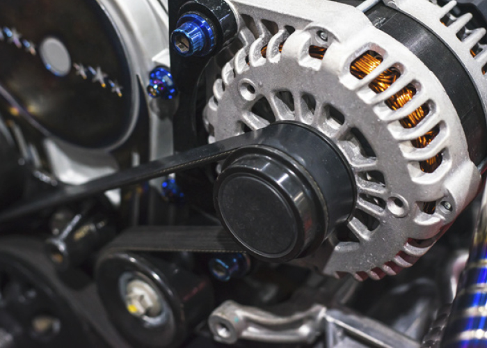
Alternators have been used to charge the 12V DC electrical systems in vehicles since long before computers and networks were part of the equation. Just a few decades ago, the 12V DC electrical system wasn’t that vulnerable to ripple voltage. Today however, excessive ripple voltage can cause major communication issues across networks and can cause a number of communication DTCs to be set in multiple control modules.
What Causes Ripple Voltage?
The vehicle’s charging system needs to be able to supply DC voltage to power the 12V electrical system, and it needs to maintain a relatively stable power level in the process. The alternator produces an AC current that must be converted into DC current by way of a rectifier. Diodes inside the rectifier pass the negative AC current to ground. This process still leaves a very small amount of AC current in the system.
DC current will drop if a diode inside the rectifier fails, and this may cause excessive ripple voltage to enter the system. If the battery isn’t able to absorb this excessive ripple, the vehicle will likely experience communication issues.
Does Ripple Voltage Affect the 12V Electrical System? Where Does it Go?
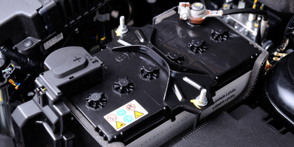
Even when the rectifier is working properly, you’d still likely be able to see 0.2-0.5V AC entering the 12V DC electrical system. Excessive ripple might cause some flickering lights or maybe an ignition problem, but it’s usually nothing too extreme. The battery is able to act as a buffer for the rest of the system by absorbing that small amount of AC voltage, preventing it from ever reaching the rest of the system.
Why Are the Networks and Control Modules So Vulnerable?
Today’s vehicles are heavily dependent upon computers and networks to perform even basic functions such as rolling the windows down or unlocking the doors. These modules operate on a lower voltage signal, typically ~5V DC. These low voltage systems are much more vulnerable to excessive ripple voltage produced by a defective alternator or rectifier.
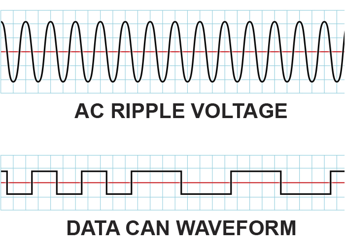
The graphs below show the waveforms of 12V AC (top) and 5V signal from a CAN-BUS network (bottom). If that 12V AC signal is able to enter the CAN-BUS, it would prevent the modules from being able to send signals back and forth.
Remember that “telephone” game we all played as kids? One person would whisper a sentence to the person next to them, then that person would relay it to the next person and so on. Now, imagine if one of those people had a mouth full of peanut butter – how well would they be able to relay the message?
The example might be a bit crude, but you get the picture. The control modules communicate with each other by way of that 5V waveform. That waveform is translated into “1s” and “0s,” triggering commands or responses from other modules or devices in the network. This communication is happening continuously whenever the ignition is on, and it is essential to vehicle operation.
How Do I See Ripple Voltage?
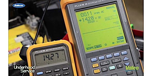
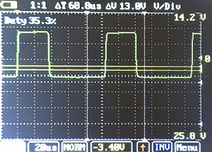
If you have the correct filter or leads, you can use a scope to view the alternating current from a diode. If the diode is functioning properly, the signal should show up as a stable waveform. If the diode is failing, you’ll see an asymmetric waveform. A DVOM, set to measure AC voltage, can also be used to test for ripple.
The alternator should be replaced if more than 50mV AC voltage is detected, though in some vehicles as much as 100mV may be acceptable. As always, it’s best to check the service information for the vehicle you’re working on.
It’s worth noting that a battery that is weak or dead may throw off a ripple test. Make sure that the battery is fully charged before starting the test.