With even the most basic vehicles having more than 10 modules connected to hundreds of circuits, there is always a possibility that wires can get crossed. Engineers want to prevent damage to wiring, circuit boards and sensors if something goes wrong that causes a short or open. To avoid damage and possible fires, engineers have devised two strategies that can be called the “immune system” for the electrical system.
Fuses
The most basic protection is a fuse. A fuse is an electrical safety device that provides over-current protection of an electrical circuit. Inside a fuse is a strip of metal that melts when too much current flows through it. The melted metal stops the flow of current and creates an open circuit. All fuses are sacrificial components. Over-current situations can occur if there is too much resistance in the circuit, or the power is shorted to ground or even power.
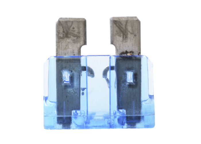
Unfortunately, fuses take time to melt and interrupt the circuit. Some fuses can take up to a second to melt during an over-current situation. Lower amperage fuses can take less time to melt to interrupt the circuit, while larger amperage circuits will take longer. Depending on the circuit and what the fuse is protecting will determine the rating of the fuse. Fuses work great at protecting circuits like electrical motors, lighting and A/C compressor clutches. But, for more delicate circuits, by the time the fuse is melted damage can be done to transistors, resistors and capacitors.
Bias Voltage
As vehicles have become more advanced, circuits and sensors have become more sensitive. So, how do engineers protect more sensitive circuits that could be damaged by an over-current situation? They test the circuit before an over-current condition occurs. This is done with bias voltage checks.
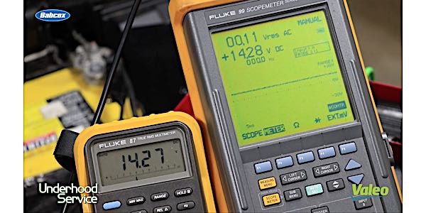
Bias voltage checks a circuit before it is active. The module sends out a voltage of a known value into a circuit. This voltage can range from two volts to full battery voltage. It is applied only for less than a millisecond. Since most circuits have a load with a known resistance, the voltage should drop to a known value. If the voltage does not drop or the circuit has a short or open, the module will deactivate the circuit to preserve the electronic components inside the module or sensor. This check takes less time than waiting for a fuse to melt. The module will then set a code for open, short or low voltage.
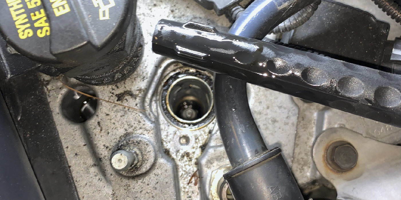
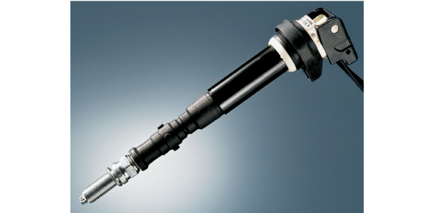
The bias voltage can cause problems for diagnostics and testing circuits in the bay. Since the circuit is deactivated, there is no current flowing to perform checks. For example, active wheel speed sensors can use anywhere between 5- and 12 volts during operation. For most wheel speed sensor circuits, when the ABS hydraulic control unit (HCU) wakes, it sends out a bias voltage signal to test the wheel speed sensor circuits. If the circuit has issues, the voltage going to the wheel speed sensor is turned off. If you look at the wiring diagram, the problem could be anywhere between the connector at the HCU to the sensor at the wheel.
Let’s say you have a wheel speed sensor circuit with an open or short in the sensor. If you were to back-probe or use a bypass connector, you would not see any voltage using a meter with the key in the ON position. But, if you use the min/max function on your meter and cycle the key, you might see voltage when the key is first cycled, and then it goes to zero. The voltage signifies the HCU is functioning and protecting the circuitry inside. Some technicians might think the HCU is defective because the other speed sensors operate as intended. But, if you are able to observe the scan tool data, you will see that the module is just trying to protect the circuit.
The important thing to remember is that if you run into a circuit or component that is not functioning, make sure you understand the circuit and how the electrical system protects the circuit.