Electricity is always looking for the path of least resistance to find ground in a circuit. This basic fundamental of direct current (DC) electricity governs how engineers design any circuit. The rule means that on one side of a circuit you have positive electricity and the other you have a ground. In between, you have a load like a motor, solenoid or other components that change the electricity into work or another form of electricity. If all or just some of the electricity can go to ground before reaching the component, the electrical part will malfunction. This basic principle of electricity has a direct connection to how the primary and secondary windings of an ignition coil operates.
Primary Circuit
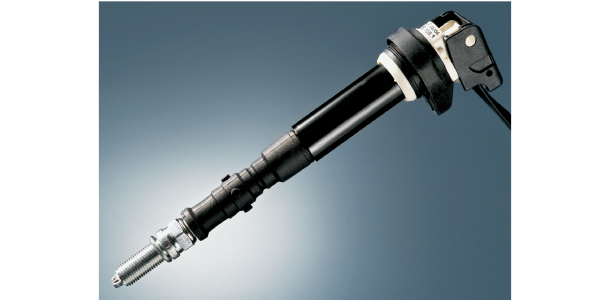
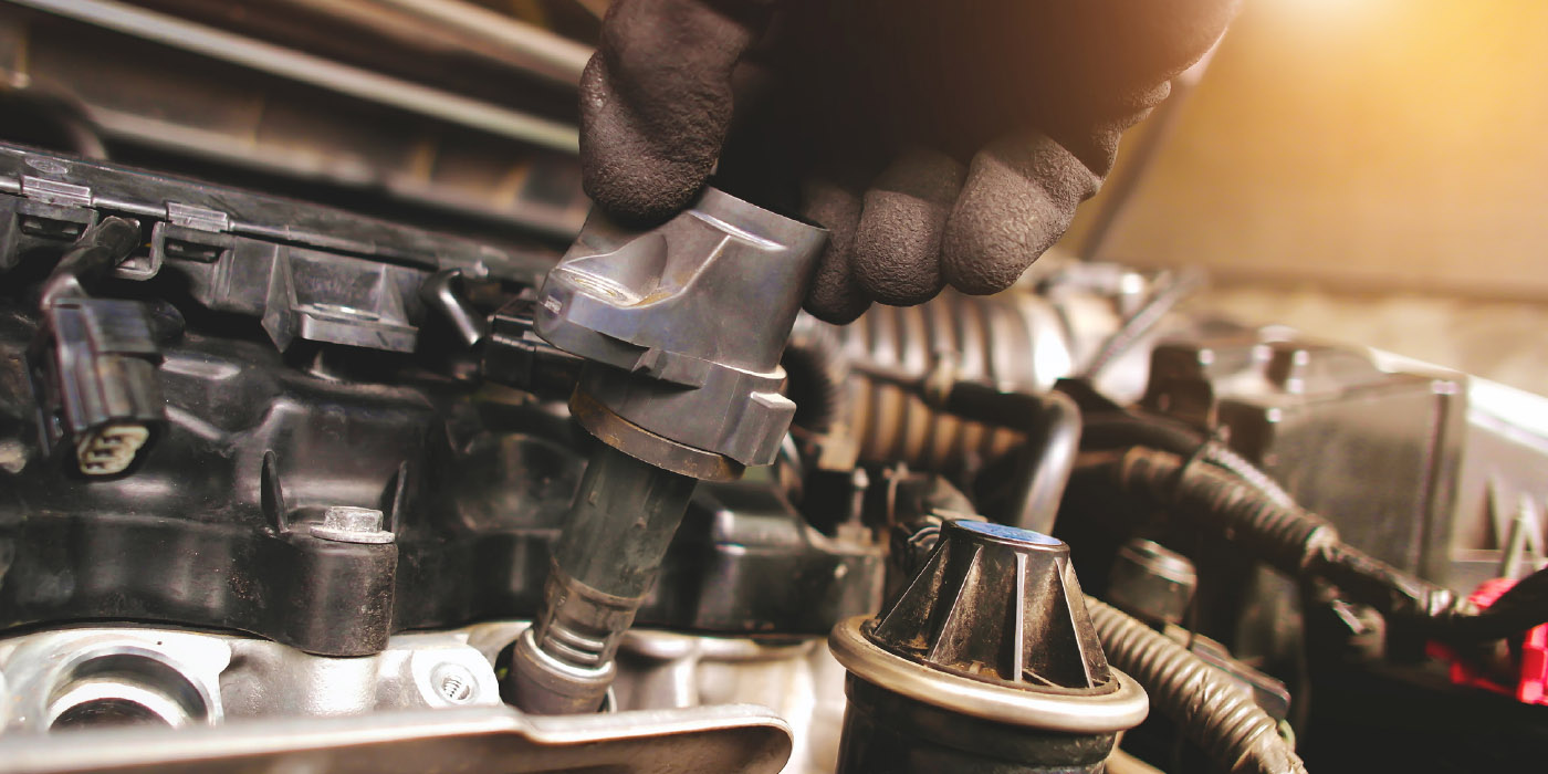
The primary windings of an ignition coil have a ground on the vehicle’s body and the positive voltage comes from a driver in the engine or ignition control module. The bad grounds to the ignition coil can reduce the amount of current flowing through a coil. The coil will have to work harder to transform low-voltage/high current energy in the primary coil into high-voltage/low-current energy in the secondary windings.
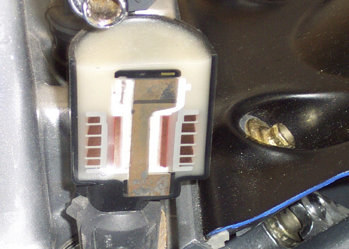
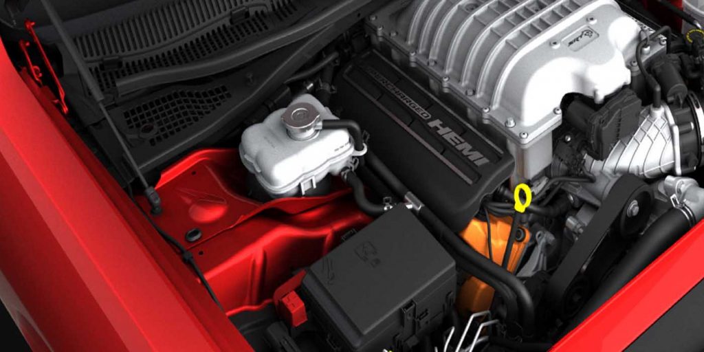
Ground wires on the primary side of the ignition coils typically use a single point on the chassis or body. The location and routing of the ground distribution can be found in the wiring diagram.
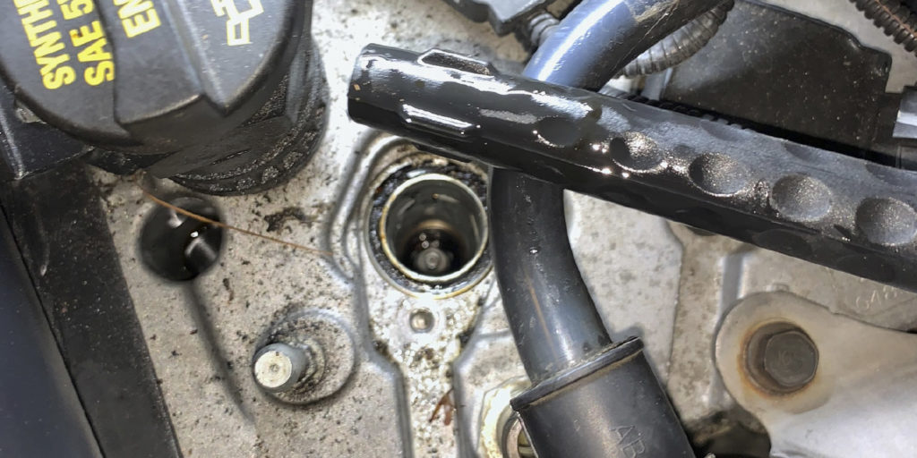
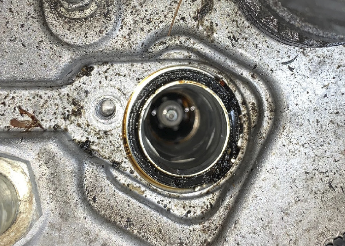
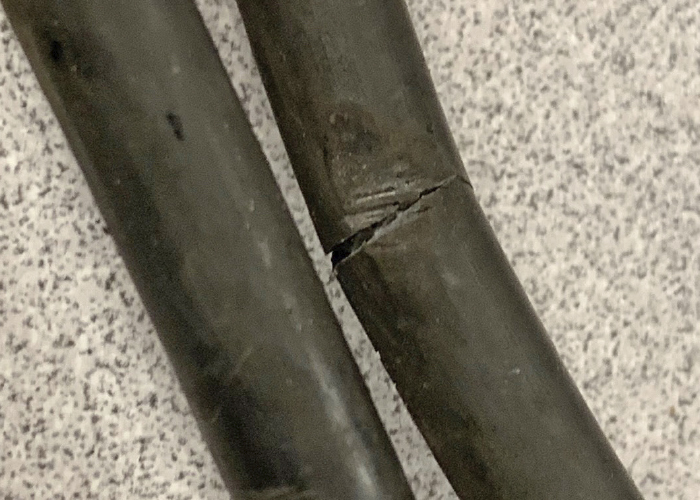
The threaded post or connectors can become corroded or damaged where the harness connects to the body. On some vehicles, the harness can be damaged by heat, leaking oil or physical damage.
To confirm the condition of the ground of the circuit, you can use a meter to test for resistance or open circuits. But, a meter will only give a limited view into the health of the circuit.
Using a low-amperage current probe and scope to measure the current “ramp” through the primary ignition circuit is perhaps the most definitive method of determining the electrical integrity of the coil and the quality of the grounds and primary windings. Many defective ignition coils, for example, will pass a resistance test but fail a current ramp test. When testing multiple coil systems, the current ramp gives an excellent comparison of current flow through each coil in the ignition system and usually helps the technician arrive at a more accurate diagnostic conclusion.
Looking at a normal waveform, there is a smooth ramp as the primary is saturated with energy. The ramp will top out and drop quickly. If the ground for the coil or circuit is damaged, the waveform will be flat or shallow compared to the other coils.
Secondary Circuit
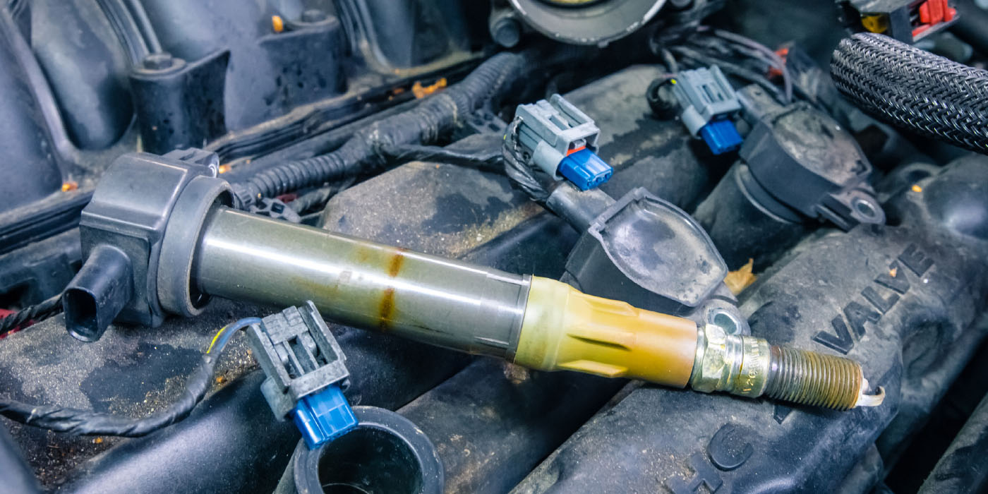
The ground or “path of least resistance” for the secondary side of the coil is the gap between the electrodes of the spark plug. If the electricity exiting the secondary can find and easier path to ground through a damaged spark plug wire, boot or grime on the side of the spark plug, it will cause a misfire.
The gap between the electrodes of the spark plug is like a resistor. As the gap increases, the resistance increases. The air fuel mixture can also change the resistance between the electrodes. A lean fuel mixture has less resistance compared to a rich fuel mixture. More resistance means a weaker spark.
No matter if it is the secondary or primary side of the coil, inspecting the grounds should be one of the first tests.