Picture your local freeway. When the traffic is light, the traffic flows at the same speeds, even if there is a lane closure. As the number of cars increases for rush hour, the speeds slow down. A lane closure can cause traffic to come to a standstill.
In this example, the cars during rush hour are like load and power in a starter motor on a circuit. The lane closure is like a bad connection or damaged wire. With light traffic loads, the speed of the traffic will not slow down as lanes merge. But, during rush hour, the speeds drop and the backup builds. In an electrical circuit, the resistance produces heat.
The measurement of voltage is like the speed of the traffic. If loads are light, the voltage does not drop. As electrical loads in a circuit or traffic increase, the speed of the vehicles or the voltage drops, just like speed during rush hour.
If a connection is like a superhighway with multiple lanes, the speed or voltage does not drop as traffic or electrical loads increase. Basically, this is a simple way to imagine Ohm’s law. Voltage drop testing is like having traffic cops on one side of the freeway running radar before and after a lane closure with radar guns.
When performing a voltage drop test, you are measuring the amount of voltage dropped through part of the circuit. It is a measurement of the energy lost trying to push energy through a bad connection. Voltage drop testing compares the battery or charging voltage to the voltage at the component. The voltage drop occurs because of resistance in the circuit that supplies the pump. The resistance could be in the connectors, grounds or harness. You can’t check for a voltage drop unless the circuit is on (remember, there has to be current flow). Even if the component in the circuit won’t work at all, turn it on.
To help you understand voltage drop, let’s take a quick look at Ohm’s Law: E = I x R. Since E = voltage, I = current and R= resistance, another way to express this equation is Voltage = Current x Resistance. Therefore, when you have current flowing through a circuit with resistance, you’ll have a voltage drop.
The most common test for voltage drop is at the positive battery cable. If you were to measure the resistance through the cable or connector, it might measure within specification. When you measure the voltage at the post on the starter, the voltage might be the same as at the battery. Voltage drop testing will reveal what is happening inside the circuit when it is under load.
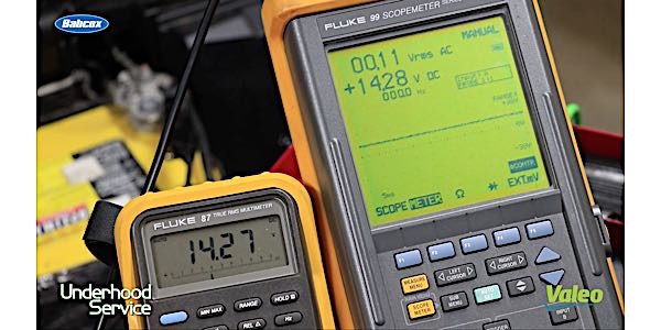
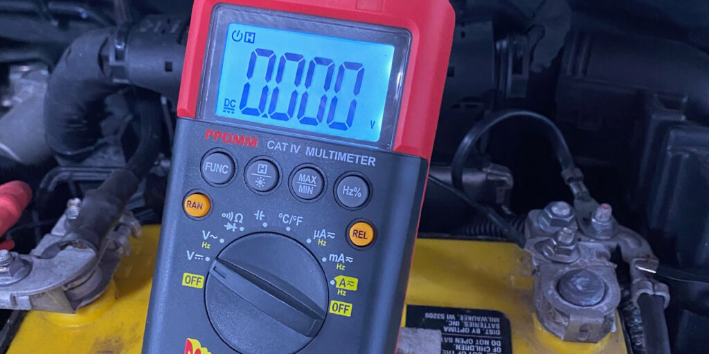
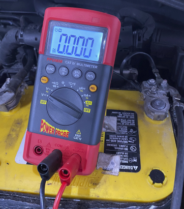
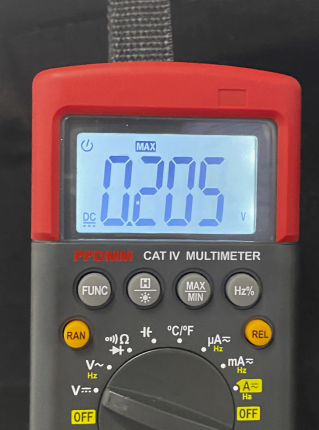
To measure voltage drop for a starter, you connect your voltmeter to the battery terminal and the post on the starter. When you turn your meter on, the display should show zero volts. Use your min/max function on the meter. Next, crank the engine. If the max voltage is voltage is greater than 0.5 volts, it is an indication that there is a problem with the cable or the connections at the battery or starter. Voltage drop testing can also be used on ground circuits and other high-draw circuits like fuel pumps, headlights and blower motors.
Since the fuel pump circuit must be energized, you will need to back-probe the connectors or pierce the wires. Some connectors can be disassembled to access the terminals. More than likely, you’ll have to pierce the wire to take a reading. It’s highly recommended to use specialized piercing probes. Using thumbtacks and pushpins can damage the connector or wires. If you damage a wire, it’s highly recommended to seal the puncture with electrical tape. Most fuel pump wiring harnesses reside in a harsh environment.
Good voltage drops occur with fuel pumps that are given multiple speeds with a module that is connected to a computer with a dedicated signal wire that tells the module to go to a lower or higher speed. Good voltage drops also come from a serial data bus, like on vehicles with a Controller Area Network (CAN) bus-controlled fuel pump module. Either way, we can control fuel pump speed by reducing the voltage, or by turning the fuel pump off and on with a pulse width-modulated output.
These types of voltage drops are fine because we want the fuel pump to run at different speeds based upon the engine’s demand for fuel. But, if it’s a system that’s supposed to have full charging voltage, such as a 12.5-volt or 14.5-volt system, and the engine’s running the fuel pump in order to make the right amount of fuel to go into the engine with a particular pulse width on the injectors, then it needs to have the correct voltage supplied to it.
While running a fuel pressure test can tell you if the pump is providing the correct amount of fuel pressure or not, it cannot tell you why it’s not producing the correct fuel pressure or volume under a wide range of conditions. Using just a fuel pressure gauge to diagnose a fuel-related problem could lead to an incomplete repair and a comeback, especially if it’s intermittent or causes problems under load.
A resistor or insulator prevents the flow of electricity in a circuit. Resistance can be caused by corrosion, fretting and even air. If you were to put a 1.0-ohm resistor in a fuel pump circuit, it would lower the 13.25 volts prior to 9.78 volts. This is a voltage drop of almost 4.0 volts. The loss of 4.0 volts may not affect the idle of a vehicle, as the fuel pressure may be within specifications. But, when more volume is required, as when the vehicle is under acceleration, it could be starved for fuel.
VOLTAGE DROP TEST PROCEDURES FOR A FUEL PUMP
- Address the negative side of the circuit first, then the positive side.
- Connect one digital voltmeter test lead to the negative battery terminal and the other to the negative terminal at the fuel pump.
- The fuel pump circuit must be energized to properly test it. Energize the fuel pump relay and power the fuel pump circuit.
- If the negative circuit is in good condition, the voltage drop measured should be 0.5V DC or less. Larger voltage drop readings indicate a problem. Damaged or corroded vehicle wiring or harness connectors are likely sources of the problem.
- Repeat the voltage drop test on the positive side of the circuit. Connect one digital voltmeter probe to the positive terminal on the battery and the other to the positive fuel pump terminal.
- Energize the fuel pump relay and power the fuel pump circuit.
- As with the ground circuit, voltage drop readings larger than 0.5V DC indicate system wiring or connector issues.