Ford Adaptive Cruise Control Alignment Process - Module Radar Sensor

Ford Adaptive Cruise Control Alignment Process

Follow these steps for proper horizontal alignment of the cruise control module radar sensor.

Models

• 2010-2017 Taurus, Explorer, Edge, Flex, Fusion, MKS, MKX, MKT, MKZ

• 2015-2017 F150, Mustang, and MKC 

• 2017 Super Duty, Escape, and Continental

This is information on setting up and completion steps for proper horizontal alignment of the cruise control module (C-CM) radar sensor.

Preparation

• Check DTCs, tires, Cruise-Control Module (C-CM) attachment/vertical alignment. 

• If any DTCs are found in an On-Demand Self-Test of the C-CM (i.e., return after clearing), the Horizontal Alignment Procedure may not run or may abort.

• If the C-CM (radar sensor) is detached from the bracket on one or more nylon ball socket joints, it must be reattached and leveled per the workshop manual before performing the Horizontal Alignment procedure. (New grommets are available for service – p/n W790214-S900)

• Once the C-CM calibration procedure is activated, a message will appear in the dual-display instrument cluster. Older style clusters will have a flashing amber symbol instead.

Vehicle Horizontal Drive Cycle Process

• The vehicle must be driven in the same key cycle.

• If a key-cycle or power loss occurs before completion of the alignment procedure, the sensor will exit the procedure. 

• The message will change to “Adaptive Cruise Not Available” for dual display clusters.

If the vehicle does not have the original equipment tires:

• Check that the tire size matches what is programmed in the PCM. If there is a mismatch, the Adaptive Cruise Control (ACC) alignment process may not complete, or the driver may experience stuttering or surging during usage of the cruise control. Upon successful completion of the alignment procedure, the “Front Sensor Not Aligned” message will clear, and normal instrument cluster display will resume. For older clusters, the amber light will cease blinking.
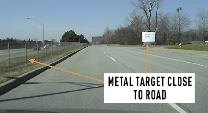
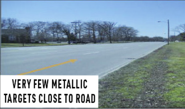
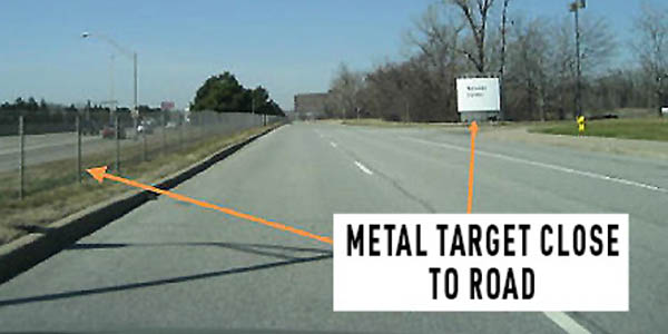
Targets

While driving the car during Horizontal Alignment mode, the radar is constantly scanning for stationary targets. Once it detects enough targets (around 250) it will align, and the “Front Sensor Not Aligned” message will disappear from the cluster.

• Driving in areas with more stationary metallic objects will align the radar faster than in areas with fewer. 

Photo 1:  shows a target-rich environment. Each post, sign and pole counts as a single target.
Photo 2:  shows a target-poor environment (very few targets) the vehicle will need a significantly longer drive time to detect enough stationary targets in order to align.

You May Also Like

Chrysler’s Totally Integrated Power Module Simplifies Circuits

The symptoms of a failing TIPM can vary depending on the vehicle. Check out your options for this repair.

TIPM is a fuse box, relay box and electronic module all in one. The electronic module is connected to several data networks.  For engineers, the module reduces a lot of wiring under the hood and passing through the firewall. The TIPM also increases the functionality of a component by allowing several inputs to control one component. 

Trakmotive Tech Tip: Window Regulator Installation

Here are eight tips to make your next window regulator replacement easier.

Multi-Spark Ignition Systems

You may have seen the stories about plasma or laser ignition systems that promise to give new life to the internal combustion engine. But while these ignition systems have yet to make it to market the latest ignition innovation still uses a coil and spark plug.

VIDEO: How Modules Manage Alternator Power

Andrew Markel discusses power flow through the electrical system on a vehicle, and how the modules help provide the right amount of power to different components. Sponsored by Valeo.

VIDEO: Checking Key Fob Signal And Operation

Doug Kaufman discusses how to diagnose key fob issues, from fixing low signal to learning new fobs after they are lost or failed. Sponsored by Blue Streak.

Other Posts

VIDEO: No-Start No-Crank On Vehicles With Transponder Keys

Doug Kaufman discusses no-start and no-crank issues on vehicles, and the different diagnostic processes and tools you can use to find the problem. Sponsored by Blue Streak.

VIDEO: Ignition Coil Circuit Testing

Doug Kaufman explains the proper diagnostic process for ignition coils in order to avoid swapping parts. Sponsored by Blue Streak.

What Kills An Ignition Coil?

Modern ignition coils are typically located between two camshafts on the valve cover and exposed to dirt and oil. But, even if a coil is mounted in a cool, clean and vibration-free environment, if the gap on the spark plug is not correct or there are issues with high resistance in the cylinder, it won’t take long for a coil to fail.

Technology Corner: Singing In The Wires

The large majority of techs in service bays right now did not have a ground-up automotive education, and many of those who did certainly did not get a ground-up electrical education. This is no indictment of anyone, just cold, hard facts.