The basic function of a valve lifter is pretty simple. It sits on the camshaft and transfers the motions of the cam lobe up through the pushrods and rockers to open and close the valves. The size and shape of the cam lobe under the lifter (multiplied by the ratio of the rocker arms) determine valve lift and duration. As such, the lifter just follows the motions of the cam. But, it does play a role in valvetrain lash (clearance) and noise.
The area of contact between the lifters and cam lobes is the highest loaded surface inside an engine, with as much as 200,000 to 300,000 psi at the point of contact, depending on valve spring pressure! Consequently, it is critical that both components have the correct geometry (both convex and taper), that both surfaces have adequate hardness to resist premature wear and failure, and that the point of contact receives good lubrication with the motor oil.
Roller Lifters
A big improvement came about with the invention of roller lifters. By placing a small wheel on the bottom of the lifter, friction between the cam and lifter was greatly reduced. That’s why all modern pushrod engines have roller lifters. Roller lifters also allow the use of more radical cam lobe profiles with faster opening and closing ramps that provide more total valve opening for a given lift and duration.
Mounting a wheel on the bottom of the lifter also changes the dynamics between the lifter and cam. A roller lifter has to be held in fixed alignment with the cam so the wheel will roll smoothly on the lobe, so you don’t want the lifter to rotate or twist.
If the original cam and lifters are still in good condition and are being reused, make sure all of the lifters are reinstalled in their original holes (same location as before). However, if the original cam is worn and needs to be replaced, replace the lifters, too. Don’t ruin the new or reground cam by reusing worn lifters.
Hydraulic Lifters
Hydraulic lifters were first developed back in the 1930s and became common in production engines in the 1950s. Hydraulic lifters eliminate the clatter produced by solid lifters and also eliminate the need for periodic adjustments by maintaining zero clearance when the engine is running. Solid lifters require a small air gap between the tips of the rocker arms and the tops of the valve stems to compensate for thermal expansion in the engine as it heats up.
Hydraulic lifters achieve zero clearance by using oil pressure against a spring-loaded plunger inside the lifter body. Oil fills the cavity under the plunger when the valve is closed. This pushes the plunger up to take the slack out of the valvetrain and hold it tight.
A one-way check valve inside the lifter holds the pressure inside the lifter as the valve opens. Hydraulic lifters are also kinder on valvetrain components than solid lifters because zero valve lash reduces the hammering effect that occurs when the valves slam shut at higher engine speeds. There’s no air gap to fill so the valve simply follows the cam lobe as it closes for a more gentle landing. This also reduces noise and helps extend the life of the valvetrain components.
Hydraulic lifters are precision-fit assemblies. The plunger is closely matched to the housing to provide minimal clearance so the leakdown rate is not too great or too small. That’s why you should never intermix the internal parts when you are cleaning and rebuilding a set of hydraulic lifters. Clean each lifter individually so the original assembly tolerances are maintained.
New Lifter Designs
The ongoing quest to squeeze more fuel efficiency out of today’s engines has lead to the development of various “displacement on demand,” “variable displacement” or “cylinder deactivation” technologies on some engines. Basically, the idea is to deactivate up to half of the engine’s cylinders when it is under light load to conserve fuel. Switching off the fuel injectors to kill certain cylinders saves fuel. But if the valves are still opening and closing, the engine is wasting energy pumping air through the dead cylinders. The valves also have to be deactivated at the same time to maximize the energy savings.
Deactivating the valves traps air in the dead cylinders. This creates an “air spring” effect that returns almost as much energy on the piston downstroke as is put in during the compression upstroke. The engine squeezes the air during the compression stroke, and the air pushes back as it expands during the downstroke.
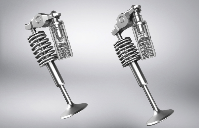
There are various ways to deactivate cylinders, including cams that have different lobes for each cylinder, changing the position of the rockers or using hydraulic lifters that can collapse on command to eliminate valve lift. A variable-position valve lifter can operate with normal plunger height or reduced plunger height. This requires a secondary oil supply hole and valving to change the position of the plunger inside the lifter.
The powertrain control module (PCM) regulates the oil pressure to the lifters via solenoid valves. With multiple-cylinder deactivation, several solenoids may be used to control oil flow to various lifter pairs. Problems with engine sensors (notably MAP, airflow and throttle position sensors), the oil flow control solenoids, engine oil pressure (if the engine is also equipped with a variable displacement oil pump), the PCM or wiring faults may all affect the normal operation of such a system.
Assembly Tips
Hydraulic lifters will normally make some noise when an engine is initially fired up, but should soon quiet down as oil fill the lifters and the lifters expand to tighten up the slop in the valvetrain. Some experts say hydraulic lifters should be presoaked in oil and bled prior to installing them. Others say this isn’t necessary and actually increases the risk of the lifters holding the valves open too far.
The normal procedure for adjusting a set of hydraulic lifters is to rotate the cam so each pair of lifters is at their lowest position on the base circle of the cam. This is done by rotating the crank so that the cylinder is at Top Dead Center on its compression stroke with both valves fully closed.