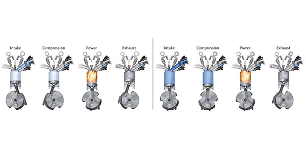
Modern engines need to know the position of the crankshaft and camshafts. Why? The timing of the valves, fuel injectors and ignition coils are continually optimized for the most efficient combustion event depending on the load and speed of the engine. But the other reason for knowing the position of the crankshaft is for misfire detection.
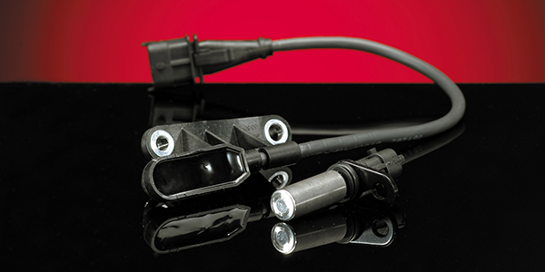
Reluctor Rings
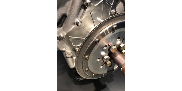
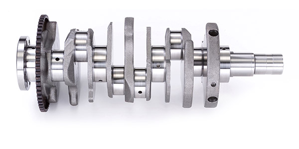
The reluctor ring or tone ring for a crankshaft position sensor is mounted on the crankshaft either on the end or in the center on some engines. On some engines, the ring is located on the flywheel.
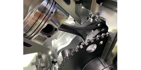
On the outer circumference of the ring are teeth, not all of which are identical. The pattern will have some larger teeth that act as reference markers that produce a reference pattern that is interpreted by the engine control module to calculate the position or angle of the crankshaft.
The crankshaft position sensor can be Hall effect, inductive or in very, very rare cases it can be optical. Hall and inductive sensors use the passing teeth to change a magnetic field or change in voltage.
The crankshaft needs to be spinning for the sensor to determine its position relative to the crankshaft. For some engines, it might take only 60 to 90 degrees of engine rotation to determine the position. On some engines there will be a second ring and sensor to improve the resolution of the sensor.
The faster the engine management system can learn the position of the crank, the faster the vehicle can start and run efficiently. The position of the crankshaft is important to direct injection vehicles – it is even more critical for stop/start vehicles with direct injection. Some systems can stop a four-cylinder engine just after top-dead-center. When the engine is restarted, a small amount of fuel is injected at the right time and ignited by the spark plug to turn the engine.
Misfire Detection
Any time you’re dealing with an internal combustion engine, there’s a chance it will develop a misfire. A better understanding of how computer systems analyze a misfire can make your job as service tech that much easier.
With most engines, the crankshaft position is the key component in determining a misfire. The engine management system calculates the time between the edges of the crank reluctor wheel teeth by receiving a signal from the CKP sensor. The crankshaft rotational velocity and acceleration are compared in the event of a power loss from each cylinder.
When a power loss is less than the calibrated value, the suspected cylinder is determined to be misfiring by the PCM. The misfire detection is enabled after certain base information is received by the PCM. Typically, engine coolant temperature, cylinder head temperature, intake air temperature and, if equipped, the mass air flow sensor (or a combination of these) are used to evaluate the condition as well as the crank and cam positions.
DTCs P0300 to P0310 indicate a random misfire per the individual cylinders. There are other codes that can be related to a misfire as well. These include P1336 (crankshaft/camshaft performance), P0606 (PCM), P0315 (CKP not learned), P0316 (misfire detected at startup), and many more. Generally speaking, the rate of misfire is calculated every 200 to 1,000 revolutions.
Almost every emission problem that causes hydrocarbons to exceed 1.5 times the federal limit will cause the check engine light to come on even if there are no symptoms noticed by the driver. On some vehicles, the PCM will disable a particular cylinder’s fuel injector if the misfire is bad enough to cause raw fuel to be sent to the catalytic converter. This is generally determined by the comparison of the up and downstream O2 sensor information sent to the PCM. When the converter’s efficiency drops below a predetermined value, the service light will turn on.
With the sensitivity of these sensors, they can generate a false misfire under certain conditions. For example, driving on a very muddy or dusty road can throw debris into the reluctor teeth (on engines with external reluctor wheels mounted on the crankshaft). Water in the fuel tank can be sent through the injectors and cause a misfire condition or even a lean condition, which can also cause the PCM to see a misfire — usually a random misfire code and not an individually isolated cylinder misfire.
Sometimes, the misfire is intermittent, which presents its own issues when it comes to diagnosing the problem. A visual check of the common causes of a misfire and monitoring the engine with a scanner under the conditions the misfire was detected is usually the best way to determine the failure point.
Some mechanics prefer using mode 6 to monitor misfires, and in some cases, that is the only option to see individual cylinder misfires. Although it can be a bit confusing when it comes to reading mode $06 information, a scope is by far my preferred method when it comes to those engine setups. Fuel pressure, cylinder compression, and all the sensors have to be in working order to keep things from misfiring.
Failure Modes
A failed crankshaft position sensor or code indicating that the signal does not correlate with the other engine position sensors, can be both mechanical and electrical.
The mechanical problems can relate to the condition of the teeth on the reluctor ring. If a tooth is missing, it changes the signal. If the ring has shifted position on the crankshaft, the signal will not correspond with the camshaft position sensor. The other mechanical issue could be the fault of the timing chain. If the chain has stretched, the signals will not match and the engine management system will set a code.
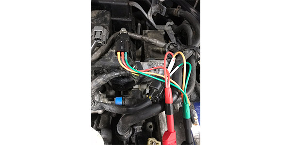
The Hall effect and inductive sensors can fail due to internal damage to the coils inside or circuitry. The damage can cause changes in resistance to the sensor. The other culprit could be the wiring to the sensor that can also change the resistance and signal from the sensor.
If the crankshaft position sensor causes a code to be set it can cause several symptoms and results. For some systems, it can cause a no start condition. In other cases, it might cause the vehicle to enter into a mode where it will use information from other position sensors and prevent conditions where misfires could occur.