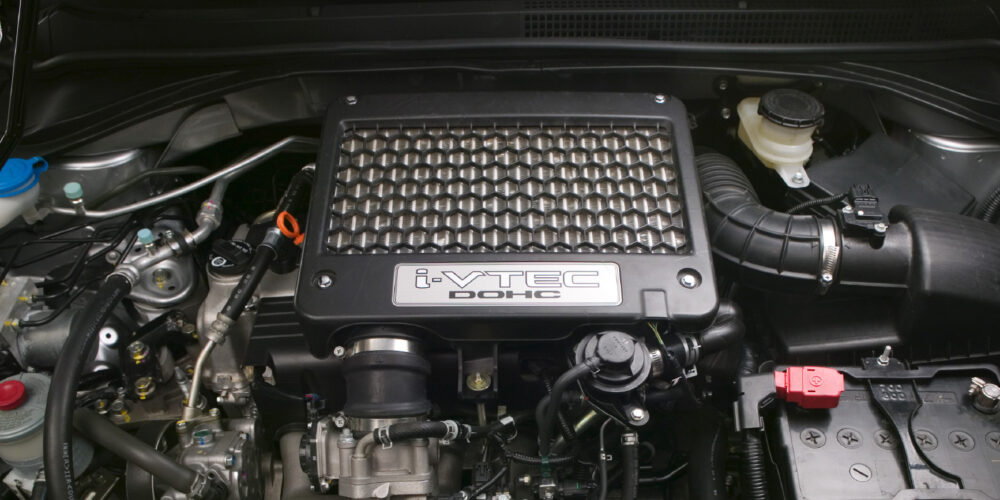
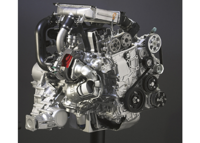
The 2007-2012 Acura RDX was Honda’s first production vehicle in North America with a turbocharger. The company took the proven K-series engine and lowered the compression ratio from 10:1 to 8:1, and added a turbocharger with the associated plumbing. But, it is a lot more complicated when it comes to managing the boost.
Acura/Honda underwent a lot of engineering in managing the boost pressure. The boost is managed with a conventional wastegate and bypass in the intake tract. Acura went a step further by placing a flap that directs exhaust gases over turbine blades for optimal performance. These components work together to manage the boost pressure and how fast the turbocharger is spinning. This prevents dreaded turbo lag or sudden spikes in power.
When diagnosing an RDX with a drivability issue related to the turbocharger, it is important to check the operation of the solenoids that control vacuum to the actuators. This can be done with a scan tool and meter.
INPUTS
The system’s main inputs are:
Boost control sensor: This sensor is located on the side of the intercooler.
Manifold air pressure (MAP) sensor: The MAP sensor is located in the intake manifold. This sensor measures pressure and vacuum after the throttle body.
Mass airflow (MAF) sensor: The MAF is located after the air filter housing. This dual sensor measures airflow and temperature of the air entering the engine.
The system also uses inputs like engine speed, throttle position and mass airflow sensor readings to determine the operation of the wastegate, intake bypass and exhaust turbine flap. The sensors work together to correlate information to determine if a change in throttle position or wastegate position produced the predicted results.
CONTROL
There are three electronic solenoids that regulate the vacuum to the actuators for the wastegate, exhaust flap and intake bypass. The solenoids are duty controlled and are either on or off. The actuators do not have position sensors; rather, the action of the solenoids is monitored through the boost pressure and MAF sensors.
If the wastegate or bypass remains open after the electronic solenoid commands it to be closed, the boost sensor will see lower-than-normal pressure. Depending on the drive cycle criteria for the code, it might cause a code P2263 (for turbocharger boost performance).
If the wastegate or bypass remains closed, it could cause an over-boost situation. This can cause the system to go into an preservation mode that prevents more boost from being generated by controlling the spark, fuel and even throttle position.
WASTEGATE
The wastegate prevents the turbo from exceeding maximum boost pressure. Like all wastegates, it diverts exhaust gases from turning the turbine. The wastegate is powered by a vacuum actuator that is controlled by an electronic solenoid that switches vacuum on or off.
The wastegate system is duty-controlled by the PCM. It is either open or closed. According to Honda, there are two duty modes or conditions – Condition A and Condition B.
Condition A occurs when the boost sensor signal is lower than the upper limit. This condition causes all of the exhaust gases to flow to the turbine and increase its rpm.
In Condition A, the PCM turns on the wastegate solenoid valve to close it. Also, it opens the passage between the turbocharger inlet connecting tube and the intake. This directs the full boost to the intake manifold.
The pressure at the wastegate control actuator is released to the turbocharger inlet connecting tube, and the spring in the turbocharger wastegate control actuator closes the turbocharger wastegate control valve.
Condition B is minimum duty when the boost sensor signal reaches the upper limit. The goal of the PCM is to slow the turbine to decrease the boost pressure. The wastegate control solenoid valve turns on to actuate the wastegate control actuator. The boost pressure from the intake air duct pushes the turbocharger wastegate control actuator and opens the turbocharger wastegate control valve. In this condition, only a portion of the exhaust gas flows through the bypass passage.
TURBOCHARGER BYPASS CONTROL SYSTEM
The bypass control system improves the boost response. The system also protects the turbocharger from the negative effects of compressor surge during high boost.
The descriptions of A and B duty mode conditions also apply to the bypass. Condition A is “on” and Condition B “off.”
When the vehicle is in cruise mode or accelerating during Condition A, the PCM turns on the turbocharger bypass control solenoid valve and opens the passage between the charge air cooler and the turbocharger bypass control valve. It also closes the passage between the intake manifold and the turbocharger bypass control valve. The boost pressure from the charge air cooler pushes the turbocharger bypass control valve and closes the passage between the charge air cooler and the turbocharger’s inlet pipe. By doing this, all boost is routed to the intake.
Condition B occurs when the solenoid valve is off. During the deceleration with the throttle valve closed, the PCM turns off the turbocharger bypass control solenoid valve. This opens the passage between the intake manifold and the turbocharger bypass control valve, and closes the passage between the charge air cooler and the bypass control valve. The vacuum from the intake manifold pulls the bypass control valve and opens the passage between the charge air cooler and the inlet pipe. By doing this, the compressed air flows from the charge air cooler to the inlet pipe to keep the turbine spinning.

TURBOCHARGER BOOST CONTROL VALVE
The boost control valve system directs exhaust gases into two passages or scrolls in the exhaust-side turbine housing. An actuator that is duty-controlled by the PCM, depending on the driving condition, moves the flap.
The door restricts the exhaust gas to one scroll at lower RPM, then flips away to allow the gas to flow through both scrolls at higher RPM. This allows the system to tune the exhaust flow over the blades of the turbine for the most efficient operation.
When the variable flap is fully closed, all exhaust gas flows to the inner scroll of the turbocharger. Under this condition, the exhaust gas speed is accelerated, and the turbocharger response is improved. When the variable flap is fully opened, the exhaust gas flows through both the outer and the inner scroll. Under this condition, the exhaust gas is efficiently used to improve the maximum boost. Because of this system, the turbocharger functions both as a quick-responding, small-sized turbocharger and a high-capacity turbocharger.
With the variable flap closed, the exhaust gas flows at high speed through the inner scroll of the turbocharger improving the turbo response. With the variable flap opened, the exhaust gas flows through both the inner and the outer scroll for efficient turbo operation at mid- and high- engine speeds.