Old vehicles with carburetors and distributors did not need to know the position of the crankshaft. As long as the technician could line up top-dead-center on cylinder #1 and match the mark on the crankshaft pulley, the timing could be set.
In the 1980s, sequential fuel injection and more precise ignition systems started to need to know the position of the crankshaft. Fuel and spark were timed with a microprocessor instead of weights and springs on the shaft of the distributor.
Modern engines need to not only know the position of the crankshaft, but the position of the camshafts. This is for variable valve timing and direct fuel injection to function. The other reason for knowing the position of the crankshaft is for misfire detection.
Rings and Magnets
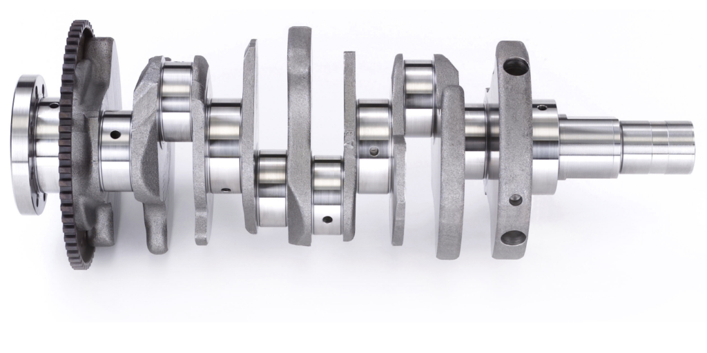
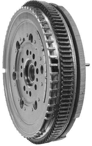
On a crankshaft is a ring with teeth called the reluctor wheel. The reluctor wheel can be mounted on the front, middle or back of the crankshaft. On some engines, the ring is located on the flywheel. The larger the diameter and number of teeth, the greater the resolution of the sensor. The teeth can vary in size to indicate a specific point in the rotation of the crankshaft.
The mechanical problems can relate to the condition of the teeth on the reluctor ring. If a tooth is missing, it changes the signal. If the ring has shifted position on the crankshaft, the signal will not correspond with the camshaft position sensor. The other mechanical issue could be the fault of the timing chain. If the chain has stretched, the signals will not match, and the ECM will set a code.
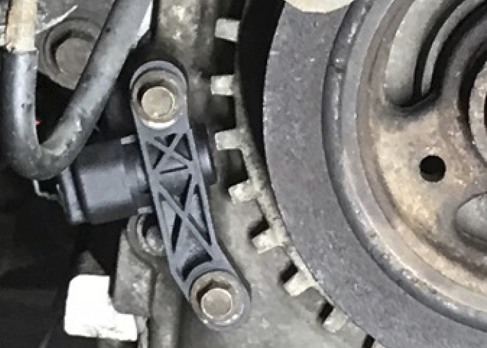
The Sensor
As the teeth pass it, the magnetic field at the tip of the sensor changes. A transistorized circuit picks up on the change and creates a signal that can be understood by the engine control module. This signal is a square wave, but some manufacturers use sharp peaks.
Modern or “digital” crankshaft position sensors have three wires. Two wires provide power and ground that is typically 5-volts. The third wire is a signal wire. The signal wire will switch between 0 and 5 volts. The switching should be square with no slope.
Some older crankshaft position sensors generate AC voltage. These two-wire sensors were not the best for fast starts because at least 250-300 rpm was required to generate an AC signal.
Electrical problems with the sensor or harness can cause extra resistance or can cause changes in resistance to the sensor. The other culprit could be the wiring to the sensor that can also change the resistance and signal from the sensor. When this happens, you may still see a pattern on the scope but the peaks will not be at five volts.
Why So Sensitive?
The crankshaft needs to be spinning for the sensor to determine its position relative to the crankshaft. For some engines, it might take only 60 to 90 degrees of engine rotation to determine the position. On some engines there will be a second ring and sensor to improve the resolution of the sensor. Also, the camshaft position sensor can be used to correlate the position.
The faster the engine management system can learn the position of the crank, the faster the vehicle can start and run efficiently. The position of the crankshaft is important to direct injection vehicles — it is even more critical for stop/start vehicles with direct injection. Some systems can stop a four-cylinder engine just after top-dead-center. When the engine is restarted, a small amount of fuel is injected at the right time and ignited by the spark plug to turn the engine.
Misfire Detection
DTCs P0300 to P0310 indicate a random misfire per the individual cylinders. There are other codes that can be related to a misfire as well. These include P1336 (crankshaft/camshaft performance), P0606 (PCM), P0315 (CKP not learned), P0316 (misfire detected at startup), and many more. Generally speaking, the rate of misfire is calculated every 200 to 1,000 revolutions.
With the sensitivity of these sensors, a false misfire can be generated under certain conditions. For example, driving on a very muddy or dusty road can throw debris into the reluctor teeth (on engines with external reluctor wheels mounted on the crankshaft).
Sometimes, the misfire is intermittent, which presents its own issues when it comes to diagnosing the problem. A failed crankshaft position sensor or code indicating that the signal does not correlate with the other engine position sensors can be mechanical and electrical.
Before you replace a crankshaft position sensor, you need to confirm the following items:
- Does the sensor have good power and ground going to the sensor? If the sensor does not have the correct voltage, it signals a problem with the harness or the module supplying power to the sensor. If power is not present at the connector, check at the module connector.
- If possible, check that the sensor has the correct resistance as specified in the service information. This includes the value for the power side of the sensor and signal to ground. Some manufacturers will not include this in the service information.
- Look at the waveform. The waveform should be well defined and switch for zero to five volts. You can compare it to a “known good” waveform. But you always need to be skeptical of a waveform. Make sure the engine and model match.
- Check all possible mechanical problems: issues related to the reluctor wheel’s condition and the relationship to the head of the sensor need to be ruled out. Some sensors are slotted, and the depth of the sensor can be adjusted.