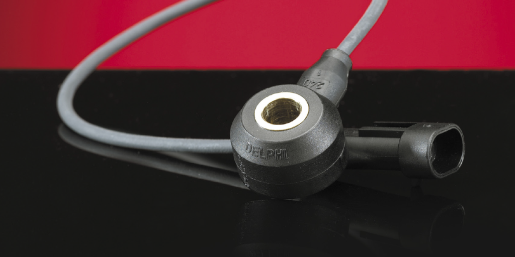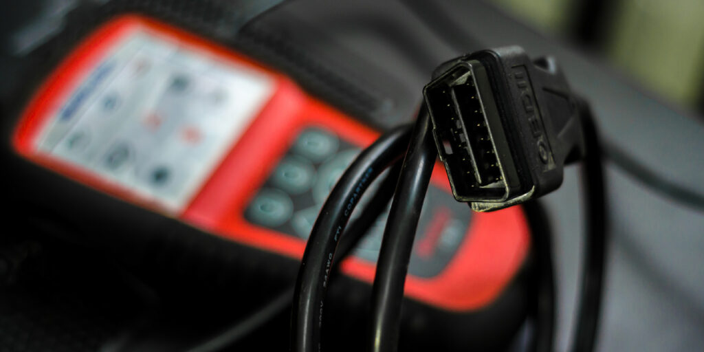
The OBDII connector is more than 25 years old, and many technicians now take this port for granted. For more than two decades the Diagnostic Logic Connector (DLC) has remained largely the same. It is more than just the location a scan tool plugs into. It is the access point which allows technicians to “talk” to the vehicle.
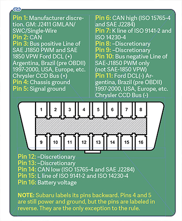
PINS 2+10: SAE J1850
SAE J1850 comes in two forms: a single wire and a dual wire. J1850 is a class B communications network interface for class 2 communications – what GM calls its single-wire J1850. Chrysler calls its single wire J1850, PCI. Ford has a two-wire J1850 standard that is a SCI bus. ISO 9141 (K-Line) is an Asian communication bus similar to J1850.
PINS 1+14: SAE J2284/ISO15765-4
If you see a code with these standards, you are dealing with a CAN bus system.
SAE J2534
SAE J2534 refers to recommended practices for Pass-Thru reprogramming. This standardizes practices so universal re-programmers can be used to reprogram certain modules. This can be performed through multiple pins, and some of the protocols are model specific.
Probing and Diagnostics
When it comes to data bus diagnostics, a lot can be done with just an OBDII connector breakout box, meter and a scope. A breakout box is an essential tool that plugs into the DLC and has a connector for a scan tool. The box has meter connections for the pins and LED lights that show activity in the circuit.
With a breakout box, it is possible to back-probe female terminals in the DLC without any damage. Just by plugging it in, it becomes a diagnostic tool by telling if there is power and ground, and even if there is bus activity. This can be extremely helpful if you are trying to diagnose a parasitic battery draw caused by a module that will not go to sleep.
If you attach a meter to a serial data bus in the breakout box (set to DC voltage), the meter will jump all over the place if the bus is active. If you have a meter with a min-max feature, you can see maybe a 0-volt minimum and a 5- or 6-volt maximum. You won’t be able to determine if the HVAC module is telling ECM to turn on the A/C compressor, but you will be able to check if the bus is active.
With a scope, it is possible to see the voltage toggling as modules are communicating on the bus. On this bus, it is possible to see two signals with different voltages. One signal is 0 and 5 volts, and the other 0 and 7 volts. The 5-volt pattern is the BCM responding to the scan tool. The 7-volt pattern is the scan tool responding. Don’t be alarmed, you may have two different levels. Sometimes the scan tool’s voltage is a little higher on the output. But, the important thing is that there are consistent square waves.
When the ignition is cycled to OFF, and the scan tool is backed out of the datastream, you will see less scope activity. You can watch the bus power down and look for signs that a module is staying awake.
It is a good diagnostics practice to look for the presence and quality of a signal with either a meter or scope. These tools and a DLC breakout box are essential tools in diagnosing and finding shorts to power and ground.