Have you ever plugged in the scan tool into the Diagnostic Communication Link (DCL) and saw a no communication message? Is it a scan tool issue or something going on with the circuits for the 16 pins in the connector?
The answer is in the DCL’s pins.
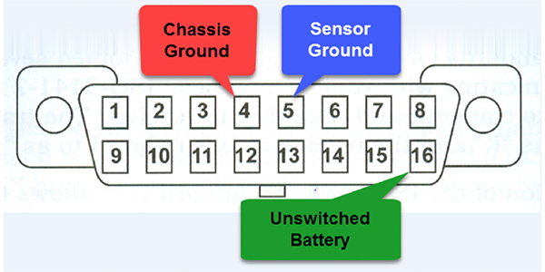
The DCL configuration has changed over the years, but three pins in the connector haven’t changed (See Figure 1). The connector provides three pin connections common to all vehicles.
Pin 16 provides constant battery vehicle power to the connector, Pin 4 provides chassis ground, and Pin 5 is sensor ground. The other pins provide communication points for a scan tool or to observe traffic on the different networks in the vehicle.
When there is no communication or the scan tool will not connect with the vehicle, the starting point is to check for battery power at Pin 16 on the DCL and good grounds in Pins 4 and 5. It is a good idea to remember that most scan tools have built-in battery power, but some code readers and older tools do not.
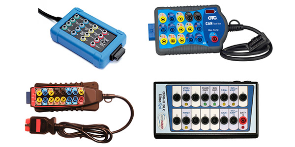
It isn’t a great practice to back probe the DCL pins, so use a breakout box as seen in Figure 2. This tool prevents damage to the pin in the DCL. This essential tool breaks out the pins in the DLC so leads with banana plugs can be connected instead of poking around the DLC with sharp probes the can damage the connection. Some breakout boxes include LED lights that indicate power in the circuit and can flash if a network is active. An OBDII breakout box can be used to diagnosis everything from bad grounds to CAN bus networks.

Check for power at pin 16 with your DVOM with the red lead and black lead at Pin 4 or 5. The meter should read the same voltage as the battery. If not, then this is the first thing to fix. Find the fuse and feed circuit in the service information and check it. In most cases, it could be a fuse or issues with connector prongs in the DLC.
The next diagnostic step is to check Pin 4 and 5 for a good ground on each circuit. The breakout box should have bright LEDs on pins 16, 4 and 5. If the LEDs are dim, always test the circuits first.
If everything checks out OK so far, then there is more to test. The breakout box shows flashing lights informing you something is going on. If your scan tool is connected to the breakout box, but will not display any datastream activity, common sense tells you to try another scan tool.
Protocols and Pins
The other 13 pins in the DLC are used for other communication protocols and networks. Before the SAE changes for CAN configuration, the DCL for OBD2 had several configurations for different protocols.
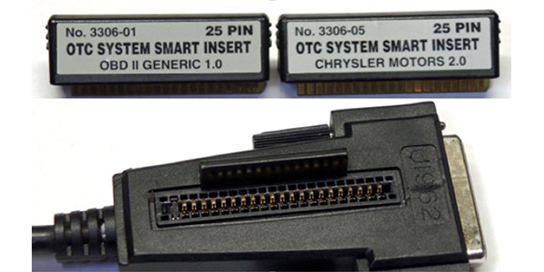
Most modern scan tools automatically select the required pins needed for talking to the right module. But before that became standard, we had keys or smart inserts that were selected for different functions as seen in Figure 3. Two smart keys may work on the same vehicle, one for generic OBD and one for manufacturer-specific communications that are in the DLC. The insert or keys routs the pins in the DLC connector to the correct connections for the scan tool’s cable. The manufacturer-specific key might be required to communicate with specific module.
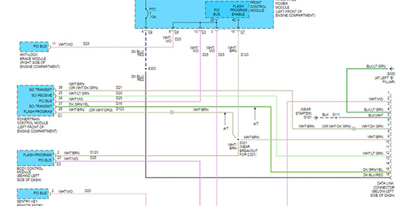
This example shows why you need to use a wiring diagram to determine which pins are used to test for proper communication as seen in Figure 4.
It uses Pin 7 for Serial Communication Interface (SCI) to communicate with ECM and Scan tool in Standalone Mode. But to use Generic OBD2, the Programmable Controller Interface on Pin 2 uses J1979.
What About Manufacturer Discretionary Pins?
Recently, I came across a 2001 GMC Savana VAN 3500 that was having brake problems. I was demonstrating to a technician a scan tool they had purchased.
The first things we discussed were the issues on the van; the brakes were not working correctly. We connected the scan tool to check for codes and got “No Communication” with the scan tool. Using the service information, we checked the number 7 fuse and it was open. Replacing the fuse restored communication. Still teaching how to use the scan tool, we proceeded to test for codes and data in other modules.
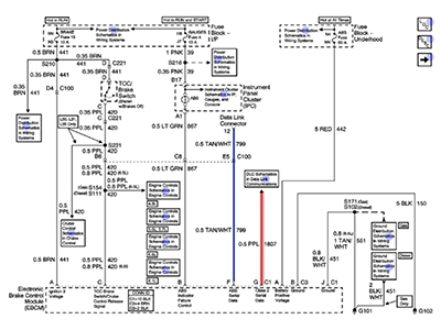
The ABS module will not communicate with the scan tool. Gathering information, we used the wiring diagram to find the pin configuration and fuses for the circuit as seen in Figure 5.
Note Pin 12 connects to the ABS module, which will not communicate with the scan tool. We replaced the missing the fuses in the feed circuits to the ABS Module. Connecting the newly purchased OBD2 breakout box, we turned the key back on and tested for communication. Pin 2 and Pin 12 are alternately flashing indicating a problem in a strange pattern that showed the signal was shorted to ground (See Figure 6).
The Message Monitor test revealed the ECM, ABS and Airbag Modules were not active on the scan tool.
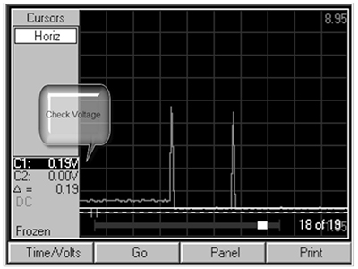
Using the scope and voltage cursors to check the voltage readings, we saw a shorted module. The circuit should not read below .2 volts, and we see no activity. Checking the wiring and the module, we found a short in the ABS module.
Keep in mind when you are checking communication issues, always use all the information available. Don’t take testing for granted by just plugging in your scan tool alone. You will be one step ahead in the process when the network codes show up.