Kia Experiences Hesitation/MIL On, DTC P0123 – UnderhoodService

Kia Experiences Hesitation/MIL On, DTC P0123

Some 2001-'06 Optima (MS) models produced between Oct. 7, 2000 and Aug. 31, 2005, equipped with the 2.5L or 2.7L (V6) Delta engine and some Sportage (KM) models produced between Oct. 28, 2004 and May 18, 2007, equipped with the 2.7L (V6) Delta engine are applicable for this bulletin.

This bulletin provides information relating to an engine hesitation or the illumination of the Malfunction Indicator Lamp (MIL) for P0123 (Throttle Position Sensor/ Switch “A” Circuit High Input).

See Figure 1.

Some 2001-’06 Optima (MS) models produced between Oct. 7, 2000 and Aug. 31, 2005, equipped with the 2.5L or 2.7L (V6) Delta engine and some Sportage (KM) models produced between Oct. 28, 2004 and May 18, 2007, equipped with the 2.7L (V6) Delta engine are applicable for this bulletin.


Figure 2

Improper throttle position sensor (TPS) values may cause the engine to hesitate under loads or cause the illumination of the MIL. To correct this condition, the TPS has been improved.

Part Number
Previous            New
35170 37100     35170 37100FFF


Repair Procedure
1. Turn the ignition key to the Off position. Open the hood and remove the engine cover.

Figure 3

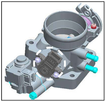
Disconnect the VIS (Variable Induction System) connector and the injector connector if equipped.

See Figure 2.

2. Disconnect the idle speed control actuator (ISCA) connector and remove the two retaining bolts. Remove the ISCA and gasket.

See Figure 3.

Figure 4

3. Disconnect the throttle position sensor (TPS) connector and remove the two mounting screws.

See Figure 4.

4. Install the new TPS sensor onto the throttle body and torque the two screws (1.5-2.5 Nm/13.2-21.6 in.-lbs.) reconnect the TPS connector.

Figure 5

See Figure 5.

5. Install a new ISCA gasket and re-install the ISCA actuator. Torque the ISCA bolts (6-8 Nm/52.8-69.6 in.-lbs.) and reconnect the ISCA connector. Reconnect the VIS connector and the injector ­connector it equipped.

See Figure 6.

Figure 6

6. Reinstall the engine cover.


Courtesy of ALLDATA.


You May Also Like

Lifter Deactivation

The area of contact between the lifters and cam lobes is the highest loaded surface inside an engine.

The basic function of a valve lifter is pretty simple. It sits on the camshaft and transfers the motions of the cam lobe up through the pushrods and rockers to open and close the valves. The size and shape of the cam lobe under the lifter (multiplied by the ratio of the rocker arms) determine valve lift and duration. As such, the lifter just follows the motions of the cam. But, it does play a role in valvetrain lash (clearance) and noise.

Alternator Testing For No Charge Conditions

Many alternator problems turn out to be nothing more than a bad connection at the alternator or a bad wiring harness.

Understanding Coolants

All-season coolant used inorganic acid technology and worked great for almost 30 years.

Ignition System Do’s and Don’ts

Why do ignition systems give technicians problems when diagnosing ignition-related misfires? The answer is that some technicians use tests that might give inconclusive results or do damage to the coil or drivers inside a module.

Tools To Service Serpentine Belts

Servicing the serpentine belt on some vehicles is a tough task.

Other Posts

Battery Charging and Diagnostics

Here are six tips to use when diagnosing a vehicle with a dead battery. 

Why Do Timing Chains Stretch?

As the timing chain wears, it can change the timing of the camshaft and crankshaft.

Carbon Deposits and Direct Injection Engines

The primary cause of these problems is that fuel and added detergents are not hitting the back of the intake valves.

Acura Turbo Engine Service

It is important to check the operation of the solenoids that control vacuum to the actuators.