One of the ways automakers squeeze more horsepower and torque from an engine is by adding variable valve timing (VVT) to the valvetrain. A conventional camshaft has fixed valve lift, duration and timing; so, the grind is always a compromise between fuel economy, performance and emissions. But with VVT, duration, valve overlap and timing can be changed on the go to optimize engine performance at different RPM, loads and operating conditions.
Valve timing can be advanced at low RPM for better throttle response and torque. Valve duration can be increased at higher engine speeds to improve breathing and power. Valve timing can also be retarded when the engine is under load to reduce NOx emissions (and eliminate the need for an EGR valve).
On DOHC engines with separate cam phasers for the intake and exhaust cams, the powertrain control module can advance or retard the intake and exhaust cams independently. This changes the centerline between the cams and the lobe separation angle, which in turn changes valve overlap and duration. On SOHC and pushrod engines such as GM’s GEN IV 5.3L and 6.0L engines, the same cam operates both the intake and exhaust valves. This means advancing or retarding the cam changes both the intake and exhaust timing simultaneously.
CAM PHASERS
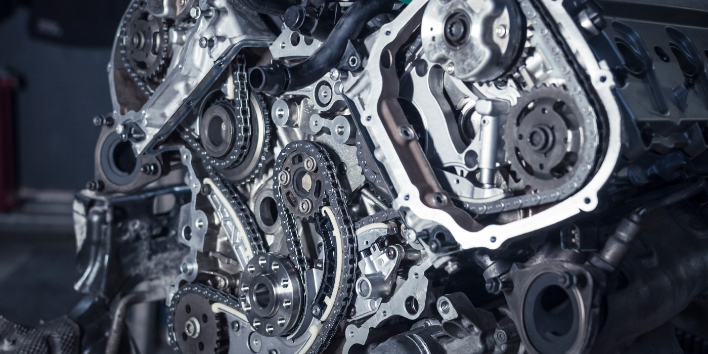
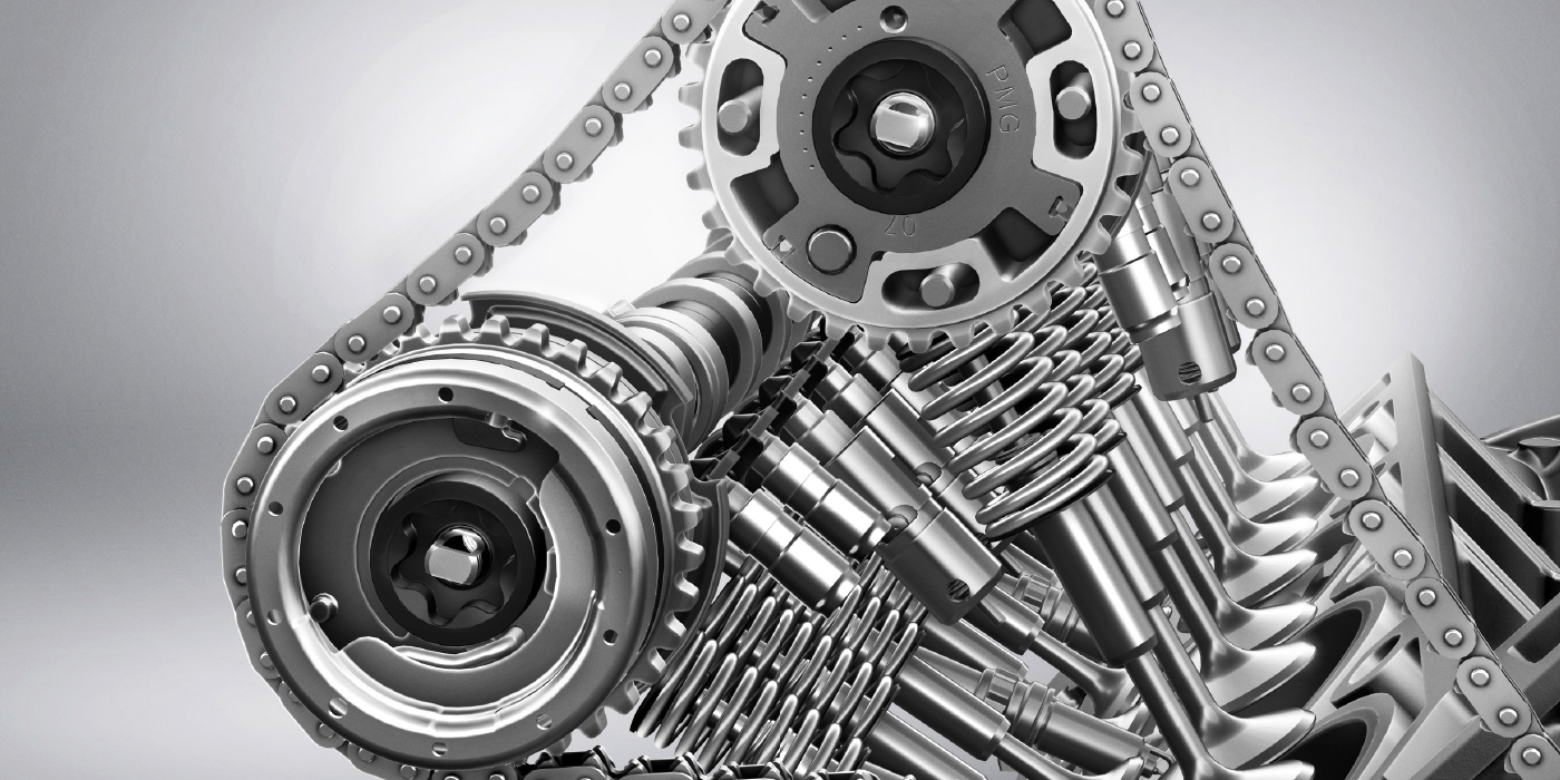
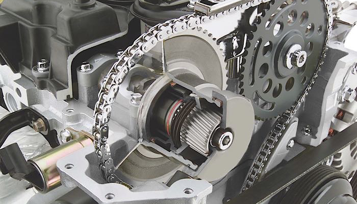
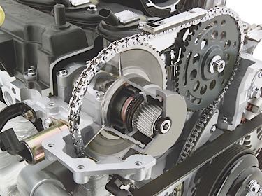
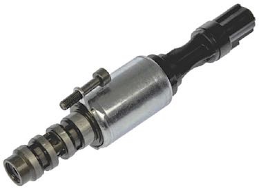
Most of the VVT systems you are likely to encounter will be those with hydraulically actuated cam phasers, although a few (such as Lexus VVT systems) use an electric actuator to advance or retard cam timing. The cam phaser changes camshaft and valve timing by rotating the relative position of the camshaft slightly fore or aft compared to its normal base timing setting. The phaser is part of the cam drive system and is mounted on the cam drive gear or sprocket. There are several basic designs:
• Helical gear phasers: These are used on many older applications and are essentially “on” or “off” actuators. When oil pressure is applied to the gear mechanism inside the phaser, it forces the helical gear to move. This typically retards cam timing 20 to 30 degrees. A spring then returns the cam back to its normal position when oil pressure is relieved.
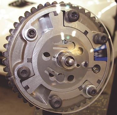
• Lobed rotor phasers: With this design, the phaser housing usually has four chambers with a movable four-lobed rotor inside. When oil pressure is routed into the chambers, it pushes the lobed rotor one way or the other to advance or retard cam timing. Many of these units provide incremental timing changes that can vary from zero degrees of advance or retard up to full advance or retard. Timing changes can range from 20 degrees to as much as 60 degrees on some applications.
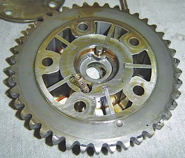
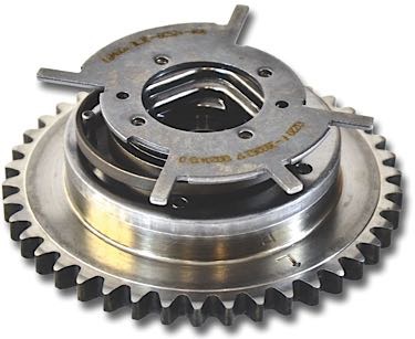
• Vane rotor phasers: These function pretty much the same as a lobed rotor phaser by offering incremental timing advance or retard as oil pressure is applied to the chambers on either side of the vanes. The phaser usually has five vanes that protrude outward from the rotor, with each vane being located within its own oil cavity.
With lobed and vane-style phasers, there is an internal dowel pin that holds the rotor in the base-timing position when no oil pressure is applied. This prevents rotor movement and noise when the engine is started and when it is idling. When oil pressure is applied to the phaser, it pushes the dowel pin out of its locating hole and allows the rotor to move.
HOW VVT WORKS
Most VVT systems are not engaged when the engine is idling and remain in the locked or base-timing setting. Also, with hydraulically actuated cam phasers, the VVT system is usually not active until the engine reaches normal operating temperature. As engine speed and/or load change, the PCM looks at its various sensor inputs and commands the oil flow control valve solenoids to open. The oil flow control valve solenoids are located near the phasers on the timing cover or valve covers.
When the solenoid valve opens, oil pressure is routed to the phaser and cam timing is advanced or retarded depending on how oil pressure is routed in the chambers inside the phaser and the design of the phaser and oil control valve. On applications that offer incremental changes in cam timing, the oil flow control valve is pulse-width modulated. Changing the duty cycle of the solenoid controls oil flow through the phaser and determines how much cam timing is advanced or retarded.
VVT PROBLEMS
As simple as it all sounds, any number of things may set a VVT-related fault code:
• Electrical problems with the cam position (CMP) sensor: The PCM has to receive an accurate cam position signal to monitor the operation of the VVT system. If the sensor has failed or is not reading accurately, it can set a camshaft position error fault code.
Cam position sensors may be magnetic or of the Hall effect variety. You can check the resistance of a magnetic sensor by backprobing with an ohmmeter (usually 500 to 900 ohms). A magnetic sensor should also produce an AC output of at least 20 mV at idle, which you can see on a scope or a scan tool that can graph voltage signals.
Hall effect sensors produce a digital signal that you can check on a scope or a scan tool that can display sensor data. The output should be an on/off square waveform. If the vehicle also provides a cam position PID and your scan tool can read it, check the value to see if it makes sense and changes with RPM and/or load.
• Electrical problems with the voltage supply, ground connection or wiring harness to the oil flow control solenoid(s): If a solenoid fails to open and close when commanded to do so, it will prevent oil pressure from reaching the cam phaser. This will also set a camshaft position error fault code.
• Low oil pressure due to a low oil level in the crankcase, worn oil pump, worn main bearings or worn cam bearings: Hydraulically actuated cam phasers require good oil pressure to change their position. If they don’t get it, cam timing won’t change. Check the oil level in the crankcase, and if low, add oil and check for oil leaks. If adding oil doesn’t remedy the situation, the phasers may not be receiving adequate oil pressure due to the other conditions just mentioned. Connect an oil pressure gauge to the oil sending unit port and see if oil pressure is within specs. If it isn’t, the engine has internal problems that will need correcting.
• Using the wrong viscosity motor oil: Most late-model engines specify low viscosity oils such as 5W-20 or 0W-20. Using a heavier multi-viscosity oil such as 10W-30 may slow the response of the cam phaser and set a fault code.
• Not changing the oil: Not changing the oil often enough may allow sludge to buildup inside the phasers. This may make the phasers slow to respond to timing change commands or even stick in a fixed position.
• Restricted valves and screens: Debris, sludge or varnish can restrict or block the oil flow control valve or cam phaser inlet screens, preventing the phasers from working properly.
• Using the wrong oil: Using the wrong oil viscosity in the engine may also make the cam phasers slow to respond, causing a camshaft position fault code to be set.
• Physical wear or damage: Physical wear or damage inside the cam phaser housing may prevent it from rotating, cause it to stick, or make the unit noisy. A broken return spring may prevent it from returning to base timing.
Think of a lobed- or vane-style cam phaser as a backwards-operating, gerotor-style oil pump. A gerotor oil pump produces oil pressure as the pump rotates. By comparison, a cam phaser rotates when oil pressure is applied to the rotor. Because of this, the clearances between the housing and rotor have to be fairly tight, otherwise internal pressure losses will adversely affect the operation of the unit.
With lobed-rotor and vane-style cam phasers, wear in the phaser housing, vanes or lobes reduces the unit’s ability to hold pressure and function normally. The dowel pin that holds the rotor in its neutral position may also become worn or shear off, or the hole that the pin fits into may become elongated or worn, preventing it from holding base timing. This can make the phaser noisy at idle as well as cause erratic valve timing.
Some late-model Ford 4.6L, 5.4L and 6.8L engines have a serious noise problem at idle due to wear inside the VVT cam phasers. The engine often clatters like a diesel at idle because of the cam phasers. Often, the right phaser is noisier than the left.
Ford TSB 06-19-8 covers its cam phaser knock problem and recommends replacing the phasers to eliminate the idle noise. But on many high-mileage engines, the cam phasers may not be functioning properly because of worn cam bearing bores in the cylinder heads. There are no replaceable cam bearings on these engines, so if the bores are worn, the cylinder heads have to replaced. However, the heads can removed and machined to accept bearings. The cam bores can also be welded and remachined back to their original dimensions to restore normal oil pressure to the cam journals and cam phasers. Replacing the original equipment front-mounted oil pump with a higher volume pump can also help remedy this situation.
REPLACING CAM PHASERS
Cam phasers are expensive units to replace, costing anywhere from $100 up to $300 each depending on the application. Various aftermarket suppliers have replacement cam phasers in their product lines, but most of the phasers that are currently available are for domestic engines (Ford, GM and Chrysler).
Although some people have tried rebuilding worn or damaged cam phasers, the OEMs treat them as a sealed unit, so no internal replacement parts or repair kits are available. Consequently, if you discover a bad cam phaser on a customer’s vehicle, you have to replace it.
CAM PHASER MODS
Cam phasers will typically advance or retard cam timing 20 to 30 degrees, and as much as 60 degrees on some applications. With this much cam movement, valve-to-piston clearances can be tight, especially if somebody wants to modify the engine with a higher lift, longer duration performance cam. To address this issue, several aftermarket suppliers have developed cam phaser limiter or lockout kits that either limit VVT advance/retard or eliminate it entirely. These kits should NOT be used as a “fix” for a noisy or defective cam phaser. They are for performance applications only.
Disassembling the cam phasers and installing a locking plate or lockout plugs defeats the purpose of the VVT system and converts the phaser to a solid gear drive. This eliminates the positive benefits of variable valve timing and may be considered emissions tampering on a street-driven vehicle. The PCM also has to be reprogrammed if a VVT lockout kit has been installed so the PCM won’t attempt to change cam timing and set VVT-related fault codes because the cams are not changing time.
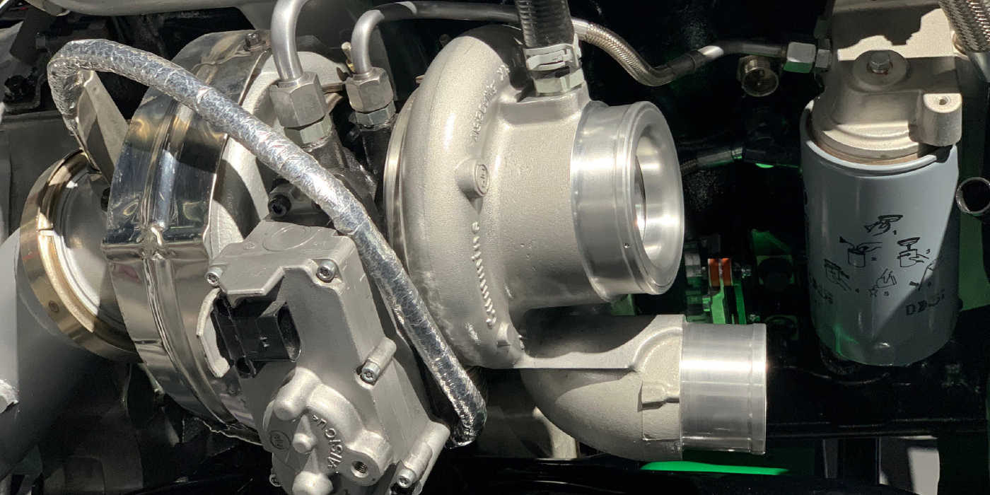
Less Lag With Variable Valve Turbocharged Engines
Turbo lag and poor throttle response at low engine speeds once made variable valve turbocharged engines only suitable for racing and high-performance applications. At lower RPMs, there is less exhaust gas to turn the turbocharger’s turbine. Also, when the driver closes the throttle, the resulting vacuum and differences in pressure can slow down the turbine further. This has been one of the disadvantages with smaller turbocharged engines where driveability is more important than peak power.
VVT can help keep the exhaust gases flowing so throttle response is improved. Traditional turbocharged engines have different camshaft requirements than naturally aspirated engines. Conventional boosted engines don’t need a lot of duration or valve overlap to fill the cylinders because the turbocharger (or supercharger) does the pushing. Less valve overlap also helps a turbo spool up faster for less turbo lag when you floor it.
With VVT valve overlap can help to keep the exhaust turbine spinning. By keeping the turbo spinning, low-end torque response is improved. This can help a small displacement engine feel more responsive and powerful. Coupled with a electronically controlled waste gate, almost all turbo lag can be eliminated.
Current automakers using this strategy include:
- Ford
- GM
- Subaru
- BMW
- Fiat/Chrysler
- Lexus
EGR Delete With Variable Valves
One item that’s going the way of the smog pump is the exhaust gas recirculation (EGR) valve. The elimination of the EGR valve is the result of the VVT’s ability to control gases entering and exiting the combustion chamber.
EGR systems are designed to reduce smog-causing nitrous oxides (NOx) by recirculating a portion of the exhaust gases from each cylinder of the engine back into the intake manifold. This process lowers the combustion temperature to under 2,500° F, above which NOx gases are formed, hurting both the environment and a vehicle’s performance.
EGR systems work, but they are not able to react fast enough or precise enough for modern engines and emissions standards. Modern variable valve timing systems are doing the same job as the EGR valve, only better.
A VVT system is able to control the timing of the exhaust valve so that the right amount of inert exhaust gases remain in the combustion chamber for the next combustion cycle. This controls combustion temperatures and the production of NOx.
If you encounter a vehicle that has higher than normal NOx levels, or a burnt or damaged pre-catalyst, make sure the VVT solenoid and exhaust camshaft position sensor are operating properly.