During the diagnosis of any turbocharged engine, you’ll almost always ask yourself, “What is the correct boost pressure?” This is a loaded question. The easiest way to discover if an engine controls the boost pressure is the desired and actual data PIDs for boost on a scan tool. On a healthy engine, these two numbers should closely mirror each other with small fluctuations. But, the “why” behind the boost pressure levels is a difficult riddle.
In simplest terms, boost pressure is determined by the speed of the exhaust turbine. The faster the turbine spins, the faster the speed of the compressor on the other end of the shaft will turn. More shaft speed means more boost. Lower engine speeds mean there is a lower volume of exhaust gases to power the turbine.
Sound simple? It’s not that easy. Most engines are their most efficient and give the best fuel economy at lower engine speeds using the tallest gear possible. Turbochargers don’t like these conditions.
In the old days, the turbocharger boost had an upper limit set by a mechanical wastegate or blowoff valve. In between the engine vacuum and the upper limit, the boost was ungoverned. The boost pressure and turbine speed were up to what was flowing in the exhaust manifold. It was a recipe for lag and sudden rushes of power.
On a modern turbocharged engine, the boost pressure and turbine speed are controlled for peak efficiency and power. This is done not with conventional wastegates and blowoff valves but with new turbine and compressor housing designs. With variable valve timing, the engine management system can control boost no matter the engine speed or load.
Wastegates
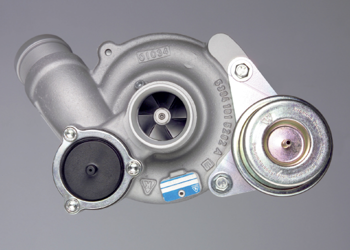
The wastegate prevents the turbo from exceeding maximum boost pressure. It diverts exhaust gases from turning the turbine. Older turbocharged engines used a line from the intake to a valve between the turbo and exhaust manifold outlet. When enough boost pressure was present, it would push against a spring and diaphragm and open the valve and slow down the exhaust turbine.
Most modern wastegates are powered by a vacuum actuator controlled by an electronic solenoid that controls the vacuum using a pulse-width-modulated signal. The valve applies a vacuum to the diaphragm connected to the control rod. Some newer turbochargers use an electric wastegate actuator that resembles an electric throttle body.
Geometry and Scrolls
Variable geometry turbochargers were used on some gasoline engines in the 1980s and early 1990s. Today, most variable-geometry turbochargers are used on diesel engines; vanes in the exhaust housing direct the flow of gases over the turbine. The position vanes control the flow of the gases over the turbine’s blades.
The vanes, plates and actuators do not stand up to high exhaust gas temperatures found in modern gasoline engines, but they work well on diesel applications.
Engineers never gave up on the variable-geometry turbochargers for gasoline engines. The same engineering concept behind variable geometry has given us dual-scroll turbochargers. These types of turbos have a turbine housing with two chambers or routes around the exhaust turbine. The two chambers direct exhaust gases over the turbine blade areas that have different pitches. One chamber could be utilized for slower engine speeds. The other might be suited for mid-range power. Both chambers can be utilized for maximum power under specific conditions.

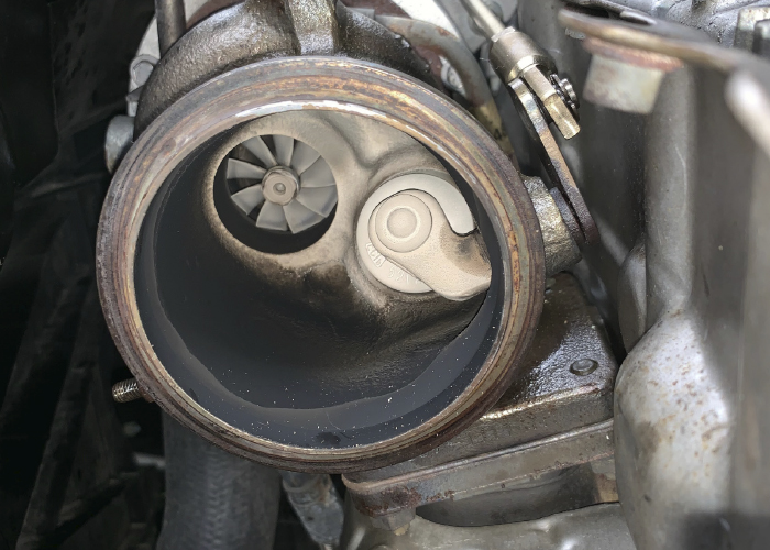
A dual-scroll turbocharger exhaust turbine housing will use a flap in the inlet to direct the flow. It is easy to mistake it for the wastegate. The position of the flap, controlled by the ECU, can reduce turbo lag by keeping the turbine spooled when the flow of the exhaust gases is lower.
Blow-Off Valve
The blow-off valve manages the pressure created by the compressor side of the turbocharger. The valve is typically on the side of the compressor housing or on the charge pipe going from the turbocharger to the intake.
The blow-off valve manages the pressure being delivered to the intake. The blow-off valve can be actuated using a vacuum signal to a diaphragm that is controlled by a solenoid. Some designs use an electric solenoid attached directly to the side of the compressor housing. The solenoid is attached to a plunger that directs the boost.
The boost pressure is typically returned to the air filter housing or compressor housing. The pressure can be vented to the atmosphere like on some performance applications.
VVT
Another strategy used by engineers is to use the valve timing to optimize the turbo and events in the combustion chamber. Original Variable Valve Timing systems had 15-20 degrees of adjustment of just the intake camshaft. Today’s systems can have 40-60 degrees of adjustment of both the intake and exhaust camshafts.
Being able to adjust the timing of the camshafts allows for more effective control of the turbocharger. The opening of the exhaust can be used to keep the turbocharger spooled up or scavenge exhaust gases from the cylinder. The overlap of the camshafts can also decrease pumping losses of the engine and even be utilized as an exhaust gas recirculation valve.
Diagnostics
Turbocharged engines run on information as much as they do gasoline. To get the actual boost pressure to match the desired or commanded boost pressure, all systems must be operating within specifications, and this includes sensors and actuators.
Think about the boost pressure sensor. When a wastegate or blowoff valve opens, the boost sensor expects to see a resulting change in boost pressure. If the boost pressure does not change, the system might assume an issue with the sensor or the actuator. While it might not immediately set a code, the monitor and criteria for the code are continuously running so a code can be set, and the check engine light will illuminate.
Some turbocharged engines use a mass airflow (MAF) sensor to determine the flow and temperature of the air entering the engine. The information from the MAF is critical in regulating turbocharger performance and air density. The information from the MAF is also used with information about air temperature sensors after the intercooler to double-check the air charge that will be entering the combustion chamber.
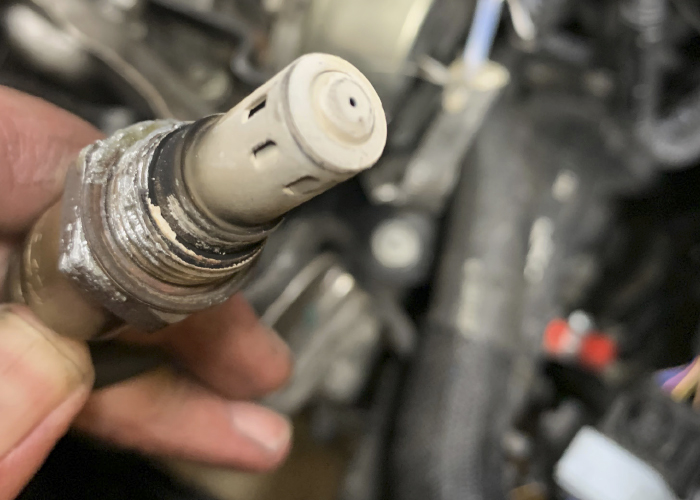
The oxygen sensor needs to be able to detect changes in exhaust temperature and oxygen content. If the oxygen sensor is contaminated or sluggish, changes in valve timing and short-term fuel trim can’t be verified.
This system of checks and double-checks can verify if a problem is electrical or mechanical in nature. While a code might not point to a specific mechanical component, it can identify an over- or under-boost condition caused by a leaking or stuck wastegate or blowoff valve.


