Use the table below to select the correct repair for the applicable model.
Year/Model Proceed To:
2002-’06 MPV 3.0L Repair Procedure A
2003-’08 Mazda6 3.0L Repair Procedure B
2001-’06 Tribute 3.0L Repair Procedure A
(built before Jan. 17, 2006)
2006 Tribute 3.0L Repair Procedure B
(built after Jan. 17, 2006)
2008 Tribute 3.0L Repair Procedure B
(engine build date
before May 16, 2007)*
2008 Tribute 3.0L Service bulletin procedure does not apply, refer to
(engine build date workshop manual, section 01-01
after May 16, 2007)*
*Engine build date can be located on the left-hand cam cover engine label.
Repair Procedure A
Caution: Before attempting a repair on a 2001-’06 Tribute, confirm if the water pump pulley is driven by the intake or the exhaust camshaft. Be sure to use the correct repair procedure. The water pump on 2001-’06 Tribute vehicles built before Jan. 17, 2006 are driven by the “intake” camshaft pulley.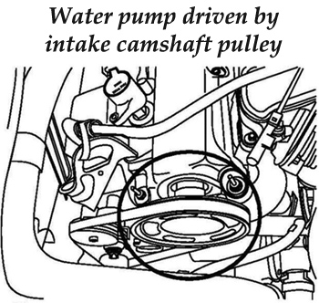
1. Verify that the water pump is driven by the intake camshaft pulley. See Fig. A1.
2. Turn on the engine.
3. Verify the customer concern by using a stethoscope and conventional diagnostics to isolate the sound. If the noise is coming from the left-hand valve cover area near cylinder #6, proceed to Step 4.
4. Turn off the engine.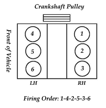
5. Remove the left-hand valve cover.
6. Rotate the engine clockwise until cylinder #6 intake cam lobes are pointing up (valves are fully closed). See Fig. A/B2.
7. Remove all intake camshaft caps (do not remove the exhaust camshaft caps).
Note: The camshaft caps must be completely lifted off, and then set back into position. Loosening and retorquing the cap bolts is not sufficient.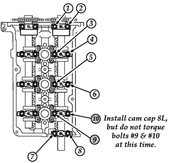
8. Reinstall all camshaft caps and torque bolts (except cam cap 8L) in the sequence shown in Fig. A3 to 8 Nm (72 lb.-in.).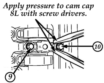
9. Using a screwdriver positioned on each side of the top of cam cap 8L, apply hand pressure and shift the cam cap toward the exhaust side of the cylinder head. See Fig. A4.
10. While holding cam cap 8L in the shifted position, torque fastener #9 (inboard) first, to 8 Nm (72 lb.-in.), then torque fastener #10.
11. Reinstall the left-hand valve cover.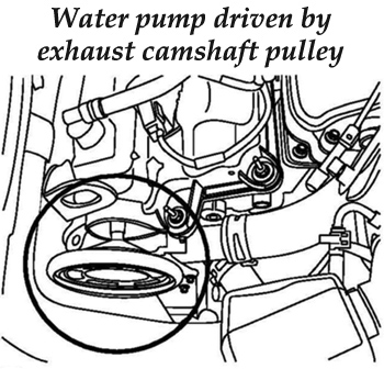
12. Verify the repair.
Repair Procedure B
Caution: Before attempting a repair on a 2006 Tribute, confirm if the water pump pulley is driven by the intake or exhaust camshaft. Be sure to use the correct repair procedure. The water pump on 2006 Tribute vehicles built after Jan. 17, 2006, are driven by the “exhaust” camshaft pulley.
1. Verify that the water pump is driven by the exhaust camshaft pulley. See Fig. B1. 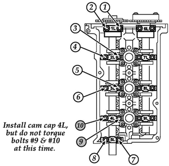
2. Turn on the engine.
3. Verify the concern by using a stethoscope and conventional diagnostics to isolate the sound. If the noise is coming from the left-hand valve cover area near cylinder #6, proceed to Step 4.
4. Turn off the engine.
5. Remove the left-hand valve cover.
6. Rotate the engine clockwise until cylinder #6 exhaust cam lobes are pointing up (valves are fully closed). See Fig. A/B2.
7. Remove all exhaust camshaft caps (do not remove the intake camshaft caps).
Note: The camshaft caps must be completely lifted off, then set back into position. Loosening and retorquing cap bolts is not sufficient.
8. Reinstall all camshaft caps and torque bolts (except cam cap 4L) in the sequence shown in Fig. 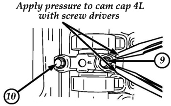 B3 to 8 Nm (72 lb.-in.).
9. Using a screwdriver positioned on each side of the top of cam cap 4L, apply hand pressure and shift the cam cap toward the exhaust side of the cylinder head. See Fig. B4.
10. While holding cam cap 4L in the shifted position, torque fastener #9 (inboard) first, to 8 Nm (72 lb.-in.), then torque fastener #10.
11. Reinstall the left-hand valve cover.
12. Verify the repair.
Courtesy of ALLDATA.