Rundle’s Rules: Ignition Coil Polarity Check
Prior to 1956, the year when most all of the domestic auto manufacturers upgraded to 12-volt electrical systems using standardized negative ground designs, some of the electrical systems on cars and trucks were positive ground and some were negative ground.
Ford used positive ground, while General Motors used both.
Chevy trucks were negative ground, while GMC trucks used positive ground. There was and still is a lot of confusion concerning the polarity of electrical systems and how to properly connect the ignition coils, as well as the battery.
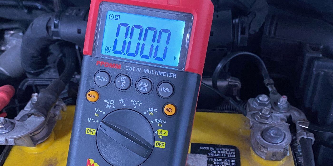
On classic and antique vehicles, you can test for correct polarity of the ignition coil by using a voltmeter.
Connect the negative lead to the (-) negative terminal and the positive lead to the engine block.
Set the meter on the highest volt range (these connections are the same whether you have a positive ground or negative ground electrical system).
The secondary winding’s polarity, which you are testing, is determined by the combined hookup of the battery and primary windings.
Crank the engine over (do not start it) and the needle of the voltmeter should show an upward swing to the plus or positive side (don’t worry about taking a reading).
If the needle swings down to the negative side and gives a negative reading, your coil is hooked up backward. To correct the polarity, simply reverse the coil primary leads.
A coil with reversed polarity will have about a 20% lower output, which may not show up at idle and low rpms, but can cause an engine to miss or stumble under load and at higher engine rpms.
This is why a technician who changes the points, condenser and other electrical components will still detect an engine miss.
The lesson here is, too often, it is "assumed" that the wiring is correct.
— Randy Rundle
Randy Rundle is the owner of Fifth Avenue Antique Auto Parts, Clay Center, KS, and services antique and classic vehicles. An author of six automotive technical books, Rundle has spent 20-plus years solving electrical, cooling and fuel-related problems on all types of antique and classic vehicles.