Models affected:
1999 Sonata
2001 Elantra, Santa Fe and XG
2003 Tiburon
2005 Tucson
2006 Azera
2007 Entourage
Automatic transaxle DTCs: P0715, P0716, P0717, P0720, P0721 and P0722
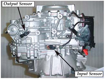
An improperly functioning input speed sensor or output speed sensor (see Fig. 1) may result in the following conditions:
• Check Engine light on;
• Harsh P-R or P-D engagement shock;
• Transaxle in third gear fail-safe; and/or
• Diagnostic trouble codes.
Parts Information:
Input speed sensor: 42620-39051 or 42620-39200
Output speed sensor: 42621-39052 or 42621-39200
Service Procedure:
1. Using a GDS, check for DTCs in both the “Engine” and “Automatic Transaxle” menus. Record the DTC(s) and description.
2. From the GDS, select:
Vehicle > “Auto Transaxle” menu > “Current Data” > “Input speed sensor” and “Output speed sensor.” Drive the vehicle and monitor the input and output speed sensors. If the sensors show:
– Continuous output, the wiring currently has no open/shorts. Go to Step 6.
– No output, go to Step 3.
3. Check the wiring harness visually for an open circuit or short circuit to ground. Check for a pinched harness at the PCM/TCM attachment bolts.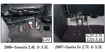
4. Disconnect the connectors at the input and output speed sensor and PCM/TCM. Check for bent pins or pins not fully inserted into the connector.
5. If a harness open/short is found, repair or replace the ECM control harness between the PCM/TCM and transaxle and go to Step 8. If not, go to Step 6.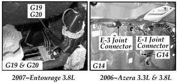
6. P0722 only: For 2006 and later Sonata and Azera, 2007 and later Santa Fe and Entourage vehicles, check the ground bolt at the location shown in Fig. 2 below and Fig. 3. Confirm the threads are clean and the bolt is tight.
7. If the ground bolts are clean and tight, follow the repair procedures shown in Chart 1.
8. Drive the vehicle for two key-on to key-off driving cycles. If the codes:
– Do not set again, return the vehicle to the customer.
– Set again, go to step 8.
Chart 1
DTC Description Repair Procedure
P0715 Input speed sensor Replace input speed sensor
– no signal
P0716 Input speed sensor
– range/performance
P0717 Input speed sensor
– no signal
P0720 Output speed sensor circuit Replace output speed sensor
P0721 Output speed sensor
– open/short
P0722 Output speed sensor
– no signal
P0700, TCM MIL request to ECM Erase code
P1529
9. Exchange a PCM or TCM from a similar year and model vehicle (excluding vehicles with an immobilizer). If the codes:
– Set again, replace the control wiring harness.
– Do not set again, replace the PCM or TCM.
Courtesy of Mitchell 1.


