A direct injection fuel pump can’t increase its speed independent of the engine to increase it’s output or pressure, so it has to control the volume of fuel that is compressed. This relationship is what makes direct injection high-pressure fuel pumps a mystery to some technicians and even engineers. But once you understand the relationship between the pump and control solenoid, your diagnostic skills will grow.
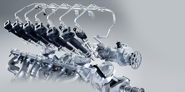
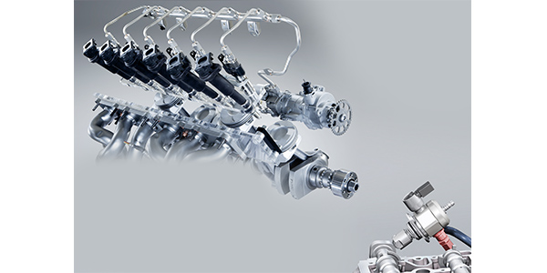
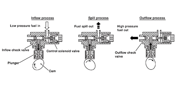
High-pressure fuel pumps are mechanical and are typically driven by a camshaft. A lobe on the camshaft pushes on a follower or roller that moves a piston. The piston in the pump has two cycles, suction and compression. The solenoid on the side of the pump controls how much fuel is compressed during the compression stroke. During the suction cycle, the solenoid will allow fuel from the low-pressure side of the fuel system to enter the pump. As the piston starts to travel upwards, the solenoid will remain open. The fuel is pushed into the low-pressure side of the fuel system when the solenoid is open. When the solenoid is shut, the low-pressure and high-pressure side of the fuel system are isolated.
If there is low demand on the engine, the solenoid will remain open longer and a smaller volume of fuel is compressed. If there is a high demand on the engine, the solenoid will close sooner, and a higher volume of fuel will be compressed. The length of time the solenoid is open will determine how much fuel reaches the fuel injectors.
The operation of the solenoid is engine-position dependent. The ECU and pump use the camshaft position sensor to know the position of the pump’s lobe on the camshaft. With engine position information, it can accurately time the events of the solenoid on the high-pressure fuel pump.
If you hook up a scope to the solenoid, you will see a “peak and hold” signal that will change as demands on the engine change. On channel B, you can graph the camshaft position sensor to understand the location of the lobe.
What If?
The supply pump in the tank also can work as a limp-home pump if the high-pressure pump fails on some engines. When this happens, it will increase the output of the supply pump, open the solenoid on the high-pressure pump and change the open times of the injectors. This engine will have restricted performance. If the supply pump is weak or failing, it has been observed on some vehicles that the suction from the high-pressure fuel pump can suck fuel from the tank and keep the vehicle running, but with a great loss of power.
Diagnostic fundamentals for GDI are not that much different than conventional fuel injection systems. These systems inject the right amount of fuel directly into the cylinder. These systems are very efficient and are able to get the right amount of fuel into the cylinder so no fuel is wasted by not having to spray on the back of the intake valve.
In fact, after working on a few GDI systems, you may find that they get easier to work on due to the tighter long-term and short-term fuel trim parameters.
GDI makes more horsepower for a given engine size. The diagnostic strategies are similar to port fuel systems, but most of these systems have an additional fuel pump, pressure sensors and a different style of injector.
With the injector in the combustion chamber, the pintle and seat of the fuel injector are under extreme pressures. To overcome the cylinder pressures, the fuel pressure supplier to the injector may be as high as 2,000 psi.
The in-tank pump in GDI systems is more responsible for volume than pressure. Fuel on this side of the system is called the low-pressure side. A fuel pump on the engine pressurizes the fuel for high-pressure injectors. This pump is driven off a lobe on the camshaft. This part of the fuel system is called the high-pressure side.
 The pressure from the high-pressure fuel pump is monitored by the Powertrain Control Module (PCM) through a sensor and can be modulated by changing the volume of fuel entering the pump inlet. While specific pressures vary among different vehicle applications, most high-pressure pumps are capable of producing at least 2,000 psi of fuel pressure. These extremely high fuel pressure levels are required to overcome compression and combustion pressures inside the cylinder and to inject a relatively large volume of fuel directly into the cylinder in a very short amount of time.
Factory and enhanced scan tools can monitor pressure transducers on the high and low sides of the system. This information can be used to diagnose the health of the low-side and high-side pumps. These tools will have the PID parameters for these components as part of the Mode 6 data. These parameters can tell you what the pressures should be during the different modes of operation. Also, if this data is used in conjunction with the waveforms of the injector pulses, it’s possible to perform cylinder balance and other diagnostic tests. The pressure transducers can also be used to monitor system pressures to diagnose hard-start problems.
Maintenance and the reduced frequency of engine oil changes have been known to take their toll on some GDI high-pressure pumps. For example, some VWs and Audis are experiencing wear on the follower on the pump due to poor lubrication and oil that has broken down. The follower that rides on the camshaft can wear and lose metal at the base.
The pump is very sensitive to the changes in dimensions of the follower and it can result in lower fuel pressures. This condition is initially diagnosed with a scan tool and not feeler gauges.
With late-model imports, so much of the diagnostic process for fuel pumps can be performed from the driver’s seat of the vehicle with a scan tool. This makes you a more productive technician and the diagnosis more accurate. And this translates into a more profitable shop.