As I’ve discovered recently, times change and so do the procedures for diagnosing inoperative fuel pumps. Just a few weeks ago, I diagnosed a case in which the owner had started his vehicle for several months by spraying starting fluid (ether) into his truck’s air intake before he cranked the engine.
The second case involved an old jobber store friend who wanted a professional diagnosis before installing his own fuel pump. After the new fuel pump was installed, his truck still wouldn’t start.
Changing my diagnostic procedure quickly solved both problems. With little more than a professional multimeter and a set of aftermarket test accessories called “relay tester jumpers,” I’ll tell you how I now approach diagnosing inoperative fuel pumps.
FUEL PUMP SYSTEMS
Before we begin, let’s take a look at the differences between diagnosing a conventional dual-line, single-line, direct fuel injection or pulse-modulated system.
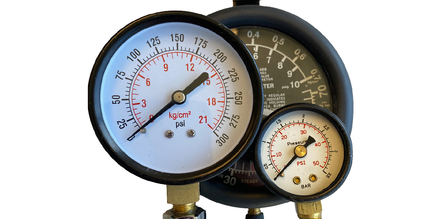
1. The fuel pump in a conventional, dual-line system supplies a fuel rail mounted on the engine, upon which a Schrader test port, the fuel injectors and the fuel pressure regulator are mounted. A mechanical fuel pressure test is standard for these systems.
2. Fuel pumps in a single-line system are mounted inside an in-tank module that also contains the fuel filter, fuel level sensor and fuel pressure regulator. Since some single-line systems don’t include a Schrader valve for fuel pressure testing, the mechanical pressure gauge must be adapted to an open fuel line.
3. Direct fuel injection systems contain a conventional or pulse-modulated fuel supply pump mounted inside the fuel tank and a mechanical high-pressure pump mounted on the engine’s camshaft cover. Since a fuel pressure sensor monitors fuel pressure, a scan tool is more useful for diagnosing fuel pump performance.
4. Pulse-modulated fuel pumps are becoming more common because the PCM can establish better fuel control and reduce pump wear by adjusting fuel pump speed to meet operating conditions. In contrast to variable-speed pumps that use a resistor in circuit to control pump speed, pulse-modulated systems control fuel pressure by rapidly pulsing or cycling the fuel pump on/off.
In any case, I’ll leave the diagnosis of direct fuel injection and pulse-modulated systems for another day because they require a different diagnostic procedure to measure and evaluate the relationship between fuel pressures and duty cycles.
SCAN TOOLS
A scan tool not only helps identify the type of fuel pump system used on the vehicle, it can also provide some very critical information. To illustrate, the Powertrain Control Module (PCM) must be functioning before the fuel pump can operate. If the scan tool doesn’t communicate with the PCM, check the 16-pin OBD II connector for applicable power, ground and communications signals.
Then, check the PCM power and ground connections before condemning the PCM. Remember, too, that communication can be interrupted if the PCM’s 5-volt reference is shorted to ground by a faulty sensor, or if the PCM’s bus communication circuits are shorted to ground by a defective body control module.
Consequently, it’s always a good practice to poll each on-board module to verify communications and to check for DTCs. Some newer-generation aftermarket scan tools will automatically perform this function, which is especially important for diagnosing modern controller area network (CAN) vehicles.
Depending upon the application, the vehicle security system might also disable the fuel pump if it detects possible theft or tampering. One case comes to mind in which the vehicle’s ignition key had lost its resistance pellet, causing the vehicle security system to disable fuel pump operation. In most cases, an appropriate DTC will be stored.
In some applications, an inertia switch that’s deactivated by a sudden jarring of the vehicle can disable the fuel pump.
Last, remember that the PCM activates the fuel pump relay only if it receives a readable signal from the crankshaft (CKP) sensor. In many applications, a good CKP will indicate cranking rpm on the scan tool or on the instrument cluster tachometer. In other applications, the PCM will indicate CKP and camshaft position sensor (CMP) activity by counting the number of signals delivered to the PCM. Keep in mind that all of these tests can be done without leaving the front seat of the vehicle.
PHYSICAL INSPECTIONS
When diagnosing any inoperative fuel pump, don’t forget to verify fuel level. To illustrate, a vehicle with just a few gallons in the fuel tank will probably not start on a steep incline. Similarly, a defective fuel level sensor might indicate a higher-than-actual fuel level, as will a fuel level sensor float that’s stuck on an improperly positioned fuel pump inlet screen.
A badly dented or damaged fuel tank might push the pump inlet out of the fuel or kink a fuel pump outlet hose. Worse still, a thief drilling a hole into the tank might have drained the fuel.
Since the possibilities are endless, I often begin a fuel pump diagnosis by adding a few extra gallons of fuel to the tank just to make sure that the pump inlet is adequately submersed in fuel.
RELAY CIRCUITS
Conventional fuel pumps are operated by a fuel pump relay that’s generally located in the underhood fuse box. The relay has four important terminals:
1. The pump B+ terminal powers the fuel pump through the relay contacts.
2. The pump B- terminal connects directly to the fuel pump and, more importantly, to the fuel pump ground.
3. The key-on B+ terminal powers the relay solenoid.
4. The key-on B- terminal is controlled by the PCM.
When the ignition is first turned on, the PCM grounds the key-on B- terminal for a few seconds to prime the system. When the engine is cranked, the PCM receives a signal from the CKP sensor and commands the relay closed for as long as the engine remains above cranking speed. Some relays also contain an optional fifth terminal that signals the PCM when the relay’s pump circuit is closed.
Although I’ve seen relay test jumpers at my local jobber stores and on tool trucks, I’ve never given a lot of thought about how they could improve fuel pump diagnosis. As it turned out in the two cases mentioned at the outset, they became invaluable.
As mentioned above, B+ voltage should be available at all times to one of the four adapter pins. Key-on voltage should be available at two pins, one B+ and the other B- or ground. Of course, the question is knowing which is which. The answer is to fabricate a small test light from a #194 light bulb and holder. The #194 bulb draws enough amperage to close the fuel pump relay, but not enough to blow the fuel pump fuse if a pin is mistakenly grounded. The #194 test bulb can also be used to verify the integrity of the pump B+ and the pump-to-ground circuits.
MULTIMETER ANALYSIS
In this application, a direct amperage reading can be obtained by connecting a DVOM ammeter to pin numbers 30 and 87. While not within the scope of this article, a fuel pump current ramp waveform can also be obtained through pins 30 and 87. Although not always true, a rule of thumb is that each ampere of current draw is approximately equal to 10 psi fuel pressure.
In any case, this test can be done without attaching a fuel pressure gauge or testing for voltage at the tank connection. As for the vehicle that would start on ether, the pump relay was closing, but the presence of B+ at both pump terminals indicated that pump itself was open-circuit. When ether was sprayed into the air intake, the engine would start and the alternator would generate enough voltage to bridge the worn brushes in the fuel pump.
The second case was fairly simple. Since I had B+ on both key-on pins, I knew the key-on pin wasn’t being grounded by the PCM. Checking the fuse box, I found a PCM fuse that had been accidentally burned. With that, I’ll leave you with a step-by-step procedure for diagnosing a fuel pump (see below) by using a relay test jumper kit available at your local jobber store or tool truck dealer.
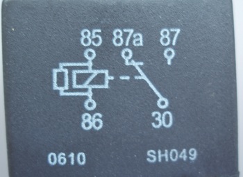
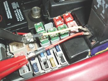
1 – The relay schematic is usually printed on the relay case. While the schematic can be confusing, it’s easy to determine pin function by using the test bulb method described in Photo 3.
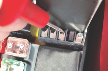 2 – The pump B+ is located on the center pin, #87, of the relay circuit tester. The key-on B+ pin, #85, is located at far right. The fuel pump feed is pin #30, left of center. Key-on B- to the PCM pin is #86, on the far left.
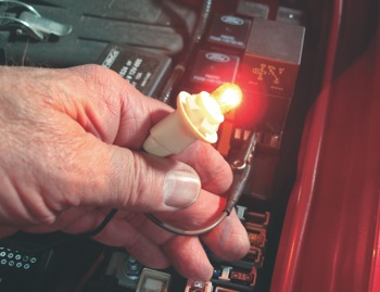 3 – A test light made from a #194 bulb and holder can be used for determining pin function and for grounding the key-on relay pin without accidentally blowing a fuse.
 4 – Amperage draw is tested by moving the positive test lead on your DVOM to its 10-amp test port. The relay’s #30 and #87 pins can be connected to the DVOM via jumper test leads or by directly holding the DVOM test probes on the relay tester pins.
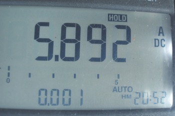 5 – The key-on, engine-off amperage flow through the pump-to-ground pin is 5.892 amps. If the relay contacts close, the key-on, engine running amperage through pins #30 and #87 will decrease to about 0.38 amps. Higher amperages might
 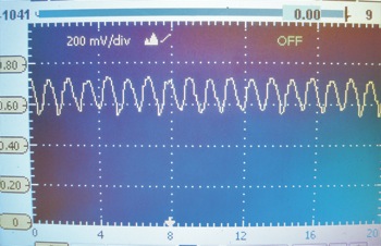 indicate that the relay contacts have excessive resistance. Zero amperage indicates that the pump-to-ground is open-circuit. Lower-than-normal amperage indicates an insufficient fuel supply to the pump.
6 – This labscope waveform indicates about 6.5 amps of current flowing through the fuel pump-to-ground pin. The ripples at the top indicate voltage fluctuations caused by the brushes traveling over the pump motor’s commutator segments. Given an eight-segment commutator, the indicated key-on, engine-off pump speed is about 6,000 rpm.