Old vehicles with carburetors and distributors did not need to know the position of the crankshaft. As long as the technician could line up top-dead-center on cylinder #1 and match the mark on the crankshaft pulley, the timing could be set.
In the 1980s, sequential fuel injection and more precise ignition systems started to need to know the position of the crankshaft. Fuel and spark were timed with a microprocessor instead of weights and springs on the shaft of the distributor.
Modern engines need to not only know the position of the crankshaft but the position of the camshafts. This is for variable valve timing and direct fuel injection to function. The other reason for knowing the position of the crankshaft is for misfire detection.
Rings and Magnets
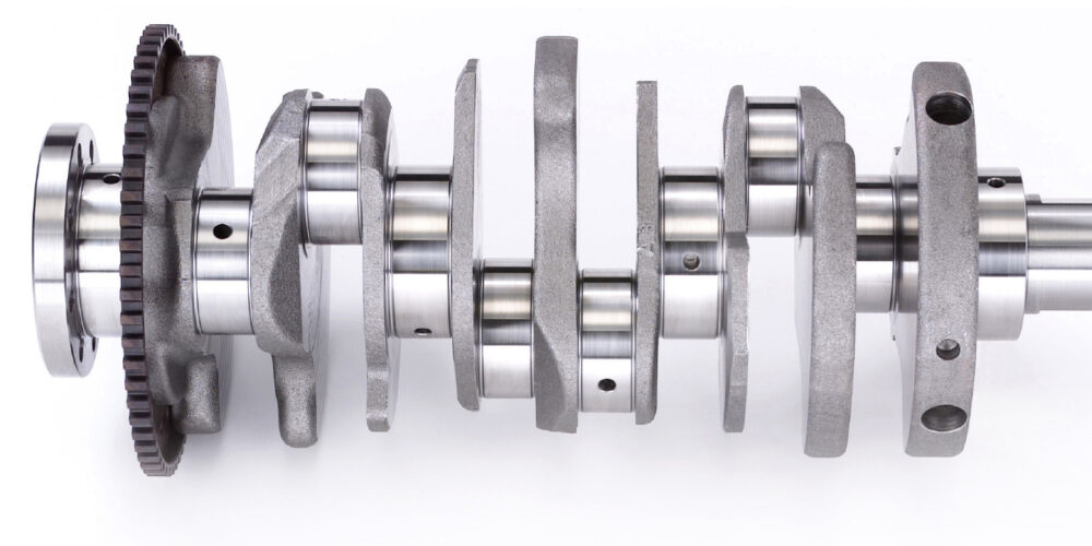
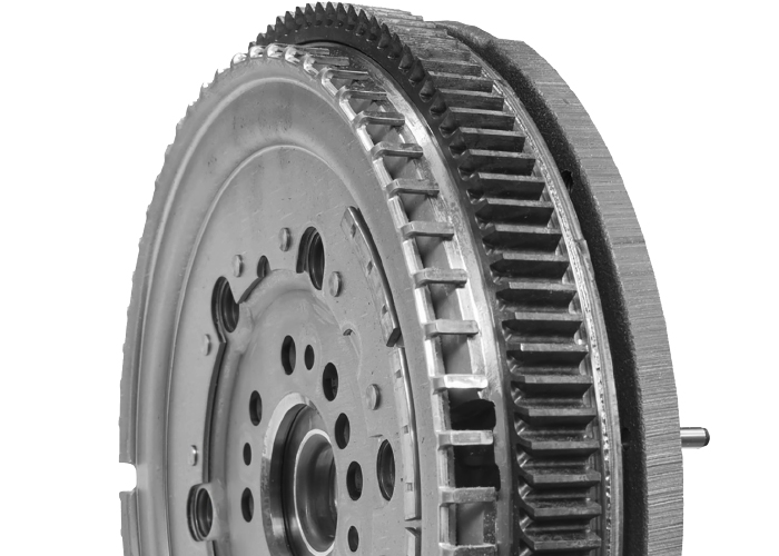
On a crankshaft is a ring with teeth called the reluctor wheel. The reluctor wheel can be mounted on the front, middle or back for the crankshaft. On some engines, the ring is located on the flywheel. The larger the diameter and number of teeth, the greater the resolution of the sensor. The teeth can vary in size to indicate a specific point in the rotation of the crankshaft.
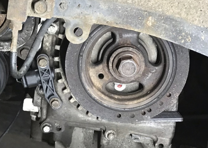
The mechanical problems can relate to the condition of the teeth on the reluctor ring. If a tooth is missing, it changes the signal. If the ring has shifted position on the crankshaft, the signal will not correspond with the camshaft position sensor. Another mechanical issue could be the fault of the timing chain. If the chain has stretched, the signals will not match, and the engine management system will set a code.
The Sensor
As the teeth pass it, the magnetic field at the tip of the sensor changes. A transistorized circuit picks up on the change and creates a signal that can be understood by the engine control module. This signal is a square wave, but some manufacturers use sharp peaks.
Modern or “digital” crankshaft position sensors have three wires. Two wires provide power and ground that is typically 5-volts. The third wire is a signal wire. The signal wire will switch between 0 and 5 volts. The switching should be square with no slope.
Some older crankshaft position sensors generate AC voltage. These two-wire sensors were not the best for fast starts because at least 250-300 rpm was required to generate an AC signal.
Electrical problems with the sensor or harness can cause extra resistance. can cause changes in resistance to the sensor. The other culprit could be the wiring to the sensor that can also change the resistance and signal from the sensor. When this happens, you may still see a pattern on the scope but the peaks will not be at five volts.
Why So Sensitive?
The crankshaft needs to be spinning for the sensor to determine its position relative to the crankshaft. For some engines, it might take only 60 to 90 degrees of engine rotation to determine the position. On some engines there will be a second ring and sensor to improve the resolution of the sensor. Also, the camshaft position sensor can be used to correlate the position.
The faster the engine management system can learn the position of the crank, the faster the vehicle can start and run efficiently. The position of the crankshaft is important to direct injection vehicles — it is even more critical for stop/start vehicles with direct injection. Some systems can stop a four-cylinder engine just after top-dead-center. When the engine is restarted, a small amount of fuel is injected at the right time and ignited by the spark plug to turn the engine.
Misfire Detection
DTCs P0300 to P0310 indicate a random misfire per the individual cylinders. There are other codes that can be related to a misfire as well. These include P1336 (crankshaft/camshaft performance), P0606 (PCM), P0315 (CKP not learned), P0316 (misfire detected at startup), and many more. Generally speaking, the rate of misfire is calculated every 200 to 1,000 revolutions.
With the sensitivity of these sensors, a false misfire can be generated under certain conditions. For example, driving on a very muddy or dusty road can throw debris into the reluctor teeth (on engines with external reluctor wheels mounted on the crankshaft).
Sometimes, the misfire is intermittent, which presents its own issues when it comes to diagnosing the problem. A failed crankshaft position sensor or code indicating that the signal does not correlate with the other engine position sensors can be mechanical and electrical.
Before you replace a crankshaft position sensor, you need to confirm the following items:
- Does the sensor have good power and ground going to the sensor? If the sensor does not have the correct voltage, it signals a problem with the harness or the module supplying power to the sensor. If power is not present at the connector, check at the module connector.
- If possible, check that the sensor has the correct resistance as specified in the service information. This includes the value for the power side of the sensor and signal to ground. Some manufacturers will not include this in the service information.
- Look at the waveform. The waveform should be well defined and switch for zero to five volts. You can compare it to a “known good” waveform. But you always need to be skeptical of a waveform. Make sure the engine and model match.
- Check all possible mechanical problems: issues related to the reluctor wheel’s condition and the relationship to the head of the sensor need to be ruled out. Some sensors are slotted, and the depth of the sensor can be adjusted.
Setting Up To Capture The Pattern
Capturing the waveform generated by a crankshaft position sensor can tell you a lot about the sensor and the engine. With the information, you can assess the condition of the timing chain, reluctor wheel and sensor.
Probes
There are a few ways to connect to engine position sensors:
- Breakout Harness: This type of harness can be installed between the connectors. This is the least invasive and will not damage the connector or harness.
- Back Probing: If you can access the connector, you can use a pin probe to the back of the connector. Don’t push too far.
- Piercing Probes: If you can’t access a sensor’s connector because it is located deep in the engine, you can use a piercing probe. But, always repair the insulation.
Triggers
No triggers should set on your scope. But, for some patterns a downward slope trigger might help to stabilize the pattern.
Voltage Scale
Most crankshaft and camshaft sensors use a five-volt signal, so a ±10 volt axis works. A few sensors use a 12-volt signal. A ±20 volt axis will work on these.
Time: The crankshaft has to turn twice to get one revolution of the camshaft. This means that 720 degrees of crank rotation equal 360 degrees camshaft rotation. You will need at least three revolutions of the crankshaft to compare the relationship to the camshaft(s). Adjust your time scale to capture at least three turns of the crankshaft on a screen.
Inductive sensor setups typically have two signals. One will be a positive voltage, and the other will be a negative voltage. They should be a mirror image of each other.
RUNNING THE TEST
Once you get your scope connected, you can run the test either cranking or at idle. Revving the engine will not improve the waveform.
Let the engine run and fill the buffer of the scope. In some cases, you will need to deactivate the variable valve timing by either disconnecting the actuator or solenoid. Another method is using a scan tool with bi-directional code.
ANALYZING THE WAVEFORM
Depending on the scope you own, you should have between 24 and 32 frames of the waveform. You are looking for a screen that has three or four revolutions of the crankshaft.
Most crankshaft signals will have an area of the ring where the teeth are spaced out or are a different size. It is impossible to say if these indicate top dead center or another event. But these can help you spot 720 degrees of crankshaft rotation. During this time, you will see one rotation of a camshaft.
Hall-effect and inductive sensor waveforms should be clean and the corners or peaks should be sharp. A clean power signal and ground are essential for a hall-effect sensor to operate. If the power going in has a lot of “hash” or interference, the signal coming out will have also have the hash.
If there is resistance in the sensor’s circuit or connector, the signal will change in height/voltage on the screen. The smallest amount of corrosion can have a huge impact on the signal, and if the ECM can read it. If the signal’s peak drops below a specific value, like three volts, it will set a code.
When comparing the waveforms, your known good waveform might come from a different scope and settings. The peaks could appear to be wider or skinner, but the patterns should match. If the base engine timing is off, the patterns will not line up.