 Applied vehicles:
2005-’06 Nissan Altima (L31) — QR25DE* engine only; 50-state emission specification only.
Action
If you confirm DTC P0420 (Catalyst System Efficiency Below Threshold) is stored in the ECM, determine if this bulletin applies by checking the ECM part number (by performing Step A in the Service Procedure). If this bulletin applies, reprogram the ECM and perform P0420 DTC Confirmation (Steps B and C in the Service Procedure).
If this bulletin does not apply, refer back to ASIST and the Electronic Service Manual (ESM) for further diagnostic and repair information.
Important: The purpose of this Action is to give you a quick idea of the work you will be performing. You must closely follow the entire Service Procedure as it contains information that is essential to successfully completing this repair.
Service Procedure
Step A: Check and Compare the Current ECM Part Number (P/N)
1. With Consult-II (C-II) on, print the ECM P/N as follows:
[START (Nissan)] – – [ENGINE] – – [ECM PART NUMBER] – – [COPY]
– You will use the ECM P/N to see if this bulletin applies.
– Leave C-II connected to the vehicle at this time.
2. Compare your vehicle’s ECM P/N to those shown under Current ECM P/N in Chart A at the bottom of this tech tip.
– Use the ECM P/N printout.
Note:
– Some states may have both ULEV (50-state emissions) and CAL SULEV (California emissions) level vehicles.
– It is best to refer to Current ECM P/Ns (above) to determine the vehicle configuration.
– If your vehicle’s ECM P/N matches one of the Current ECM P/Ns in the chart above, this bulletin applies. Continue with this procedure and perform Steps B and C.
– If your vehicle’s ECM P/N does not match one of the Current ECM P/Ns in the chart above, this bulletin does not apply. Refer back to ASIST for further diagnostic and repair information.
Step B: Reprogram the ECM
ECM Reprogramming Overview
There are four basic steps:
Step One: Download reprogramming data (transfer it) from ASIST into C-II.
Step Two: “Preparation” steps before reprogramming.
Step Three: Reprogram the ECM.
Step Four: ECM reprogramming “Wrap-up.”
If you are familiar with ECM reprogramming: review the following Steps 1-4. Use them as a quick reference for ECM
reprogramming.
Step One: Download Reprogramming Data (transfer it) from ASIST into C-II.
Caution:
• Connect a battery charger to the vehicle battery. If the 12V battery voltage drops during reprogramming, the ECM may be damaged.
• Make sure C-II is connected to the AC power supply. If the C-II battery voltage drops during ECM reprogramming, the ECM may be damaged.
• Be sure to turn off all vehicle electrical loads. If a vehicle load remains on, the ECM may be damaged.
1. Select vehicle model and model year.
2. Select the correct Reprogramming Data:
a. Locate the specific “Vehicle Configuration” (Example: A/T, ASCD).
 Note: Vehicle Configuration may include items such as engine type, transmission type and vehicle options such as ASCD, TCS, ABS, etc.
b. Select (click on) the “To” number for your Vehicle Configuration for the Reprogramming Data. (Write the “To” number on the repair order.) Note: The “To” number will read: 23710-XXXXX.
3. Click on the “Add” button. This will add the selected data to the “File(s) Selected” list.
4. Click on “Continue” and follow the on-screen directions to perform “data transfer” (download) from ASIST into C-II.
Step Two: Preparation Steps Before Reprogramming
1. Connect a battery charger to the vehicle’s battery.
– Set the charger to a low charge rate (trickle charge).
Caution: For number 2 and number 3 below, do not connect the C-II AC power supply.
2. Press [SUB MODE] then:
a. From the listed items, find and select [BATTERY CHARGE]
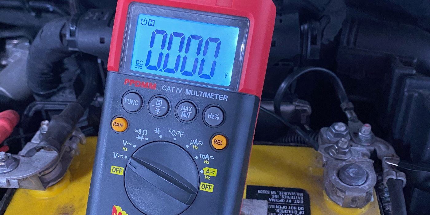
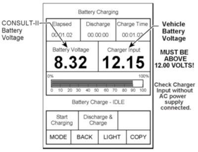
3. Check the C-II “Charger Input” reading (see Figure 1).
Note:
– “Battery Voltage” is the voltage level of the Consult-II battery.
– “Charger Input” is the voltage level of the vehicle’s battery. (It must be above 12 volts.) Caution: If the “Charger Input” is below 12 volts, a list of items to check is contained in the “ECM Reprogramming for Nissan Vehicles” General Procedure.
Step Three: Reprogram the ECM
Step Four: ECM Reprogramming “Wrap-up”
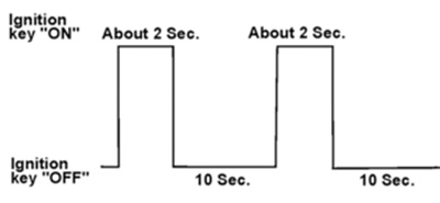
1. Turn off the ignition switch and the C-II.
2. Wait more than 10 seconds, and then:
a. Turn on the ignition switch for two seconds, and then:
b. Turn off the ignition switch again for 10 seconds (see Figure 2). This will reset ECM “self learned” data.
 3. Start the engine and check the idle speed.
– If idle speed is too low, perform “Idle Air Volume Learning” (IAVL).
– See the appropriate ESM for this procedure.
Note: If the engine will not idle, hold the engine rpm at about 2,000, then slowly bring it down to an idle. IAVL can now be performed.
4. Confirm the engine is operating normally.
5. Make sure the MIL is off.
– If it’s still on, use C-II with the Diagnostic (red/white) Card to erase any DTCs that may have stored during the reprogramming procedure.
6. Go to Step C below.
Step C: Perform P0420 DTC Confirmation Using C-II
Important: Before starting the DTC Confirmation procedure, erase all DTCs. Regardless if there are no DTCs, press the Erase button on C-II. This will reset all SRTs to “INCMP” (incomplete).
Note: If the DTC Confirmation Procedure has been previously conducted, always turn off the ignition switch and wait at least 10 seconds before conducting the next test.
Testing Condition: Do not hold engine speed for more than the specified times given below.
1. Turn on the ignition switch.
2. With C-II, select “Data Monitor” mode.
3. Start the engine and then warm it up to operating temperature.
4. Turn off the ignition switch and wait 10 seconds.
5. Start the engine and keep the engine speed between 3,500 and 4,000 rpm for at least one minute under no load.
6. Let the engine idle for one minute.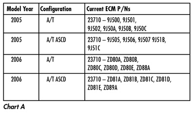
7. Make sure that “COOLAN TEMP/S” indicates more than 70° C (158° F).
8. Open the engine hood.
9. Select “DTC & SRT CONFIRMATION,” and then “WORK SUPPORT” mode.
10. Rev the engine to 2,500-3,500 rpm, hold it for three consecutive minutes, and then release the accelerator pedal completely.
11. Wait five seconds at idle.
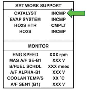
12. Rev the engine up to 2,000-3,000 rpm and maintain it until “INCMP” of “CATALYST” changes to “CMPLT” (it will take approximately five minutes).
13. If “INCMP” changes to “CMPLT”:
– Inspection and repairs in this bulletin are complete.
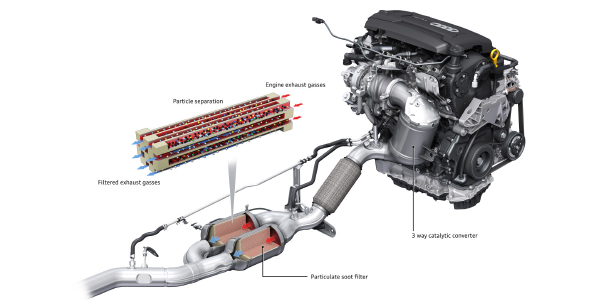
– Do not replace the catalytic converter.
14. If “INCMP” does not change to “CMPLT” (see Figure 3 for example):
– Stop the engine and let it cool down to less than 70° C (158° F), and then retest Step 1 above.
15. If “INCMP” still does not change to “CMPLT”:
– Replace the catalytic converter (exhaust manifold assembly).
– Refer to the ESM for catalytic converter replacement.
Courtesy of ALLDATA.