Applied Vehicles:
2002-’03 Maxima (A33)
2002-’06 Sentra (B15), Altima (L31)
2003-’06 350Z (Z33), Murano (Z50)
2004-’06 Maxima (A34), Titan (A60), Armada (TA60) and Quest (V42)
2005-’06 Frontier (D40), Xterra (N50) and Pathfinder (R51)
If you confirm the MIL is on with DTC U1000 (CAN COMM CIRCUIT) or DTC U1010 (CAN COMM) [2006 Models only] stored in the engine control unit, and there are no driveability incidents, determine if this bulletin applies by performing steps 1 and 2 of the below Service Procedure.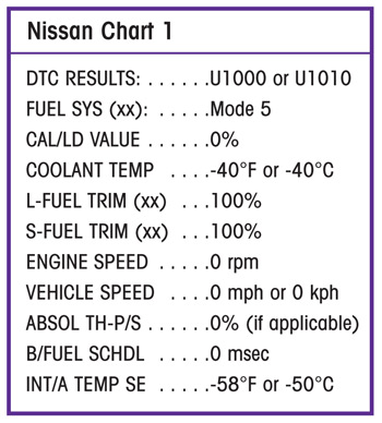
Actions:
If this bulletin applies, there may be excess resistance in certain ground connections:
– Clean/re-tighten the ECM ground connections.
– Clean/re-tighten the negative battery cable body connection and the battery post connection.
– If necessary, clean and ensure good contact between the steering member assembly and the left- side instrument stay assembly.
Important: The purpose of “Actions” (above) is to give you a quick idea of the work you will be performing. You MUST closely follow the entire Service Procedure as it contains information that is essential to successfully completing the repair.
Service Procedure:
1. Print the engine freeze-frame data using CONSULT-II.
– Refer to section EC in the appropriate service manual for freeze-frame diagnostic info.
2. Compare your printout to Chart 1.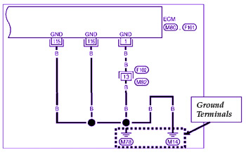
a. If your readings match exactly to the readings above, go to step 3.
b. If your readings do not match exactly, this bulletin does not apply.
– Go to section LAN in the appropriate service manual for additional diagnostic information.
3. Make sure all ECM ground terminal connections are clean and tight as follows:
a. Make a list of ground terminals for your vehicle. Refer to the appropriate service manual, section EC (Power Supply and Ground Circuits). See Fig 1.
Note: This is only an example. Your customer’s vehicle may be different.
b. Take your list and go to section PG in the appropriate service manual. You’ll be able to identify the exact location of the ECM ground terminals you’ll need to check. See Fig. 2.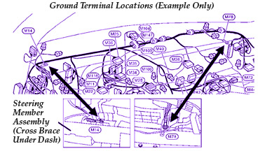
c. Now go to the ground terminal(s) on the vehicle and remove the nut or bolt that holds the terminal eyelet(s).
d. Clean the following surfaces on each ECM ground terminal. This will ensure good contact in the connections.
– Both sides of the eyelet
– Eyelet mounting surface
Note: Do not remove paint from painted surfaces in the engine compartment to improve ground. Doing so may cause corrosion/rust.
– Nut/bolt threads.
– Female threads in bolt holes (use the correct size tap).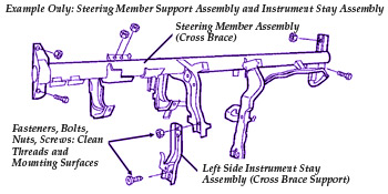
e. Reinstall and tighten the nut or bolt that holds the terminal eyelet.
4. If the ECM ground terminals are attached to the steering member assembly (cross brace under the dash):
a. Remove the fasteners (nuts, bolts and screws) that attach the left-side instrument stay assembly (cross brace support) to the steering member assembly (see Fig. 3).
b. Clean the mounting surfaces and fastener threads.
c. Reassemble and tighten the fasteners.
5. Clean the negative battery cable connections.
a. Write down all the radio presets.
b. Disconnect the negative battery cable at the battery and at the body connection.
c. Clean the following items:
– Negative cable-to-body connection eyelet (both sides)
– Body connection bolt (head and threads)
– Female bolt hole threads (use correct size tap)
Note: Do not remove paint from painted surfaces in the engine compartment to improve ground. Doing so may cause corrosion/rust.
– Battery negative post
– Negative cable battery terminal
d. Reconnect the negative battery cable (at the body and the battery).
e. Reprogram the radio presets.
6. Use CONSULT-II to erase all DTCs.
7. Test-drive and re-check for DTCs.
Courtesy of ALLDATA.