 Applicable model(s)/VINs: 2004-’09 Mazda3, 2006-’10 Mazda5
Some vehicles may experience a body vibration when driving approximately 55 mph. This symptom is due to the characteristics of the No. 3 and No. 4 engine mounts.
Modified No. 3 and No. 4 engine mounts have been established for service only. Customers having this concern should have their vehicle repaired using the following repair procedure.
Repair Procedure
Important Note:
• This repair should only be performed if all tires and rims are confirmed to be in balance and all suspension components are in proper working condition.
• Notify customers that use of the modified mounts will reduce vibration at cruising speed but may increase vibration at idle.
Note: Because idle vibration may increase, it is highly recommended to continue using mass production mounts for all other service concerns.
1. Verify the concern.
2. Replace the No. 3 and 4 engine mounts with service parts according to MS3 online instructions or Workshop Manual section 01-10 Engine Removal/Installation.
3. Center the new engine mounts as outlined in Engine Mount Centering Procedure.
4. Verify the repair.

Engine Mount Centering Procedure
No. 1, No. 3 and No. 4 Engine Mount Adjustment
1. Warm up the engine.
2. Raise and support the vehicle on a hoist.
3. Remove the engine under cover.
4. Lower the vehicle until the front tires lightly touch the ground.
5. Secure the engine and transaxle using an engine jack and attachment.
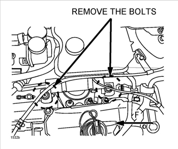
6. Remove the two bolts from the No. 3 engine mount bracket.
See Figure 1.
7. Lift the engine using a jack until the No. 3 engine mount is lifted slightly from the vehicle body.
Note: Do not raise engine too much or A/C pipe damage may occur.

8. Move the engine mount rubber or the engine until the installation hole on the vehicle body aligns with the hole in the engine mount bracket.
9. Lower the jack and tighten the bolts on the No. 3 engine mount bracket. Tightening torque: 55.0-77.3 ft.-lbf. (74.5-04.9 Nm) Note: Do not allow the engine mount bracket to be misaligned.
10. With the engine supported as described in step 5, remove the four nuts and two bolts from the No. 4 engine mount top plate. Remove the top plate.
Note: To access the mount, remove the battery box.
11. Lift the engine again using the jack until the No. 4 engine mount is lifted slightly from the vehicle body. Note: Do not raise engine too much or A/C pipe damage may occur.
12. With the top plate of the No. 4 engine mount removed, move the engine mount bottom plate or the engine until all four installation studs on the vehicle align with the engine mount holes.
See Figure 2.
13. Place the top plate back on and tighten the No. 4 engine mount bracket nuts and bolts to the torque indicated in Figure 3.
Tightening torque:
a: 32.5-45.0 ft.-lbf. (44.0-61.0 Nm)
b: 61.1-86.7 in.-lbf. (6.9-9.8 Nm)

14. Lift the engine again using the jack and loosen the two bolts on the No. 1 engine mount rubber until they are slightly loose on the No. 1 engine mount rubber.
See Figure 4.
15. Shake/rock the engine back and forth.
16. Tighten the bolts in order below.
a: Crossmember-side No.1 engine mount rubber. Tightening Torque: 68.7-86.1 ft.-lbf. (93.1-116.6 Nm)
b: Engine-side No. 1 engine mount rubber. Tightening Torque: 68.7-86.1 ft.- lbf. (93.1-116.6 Nm)
A/C Pipe Adjustment
Note: The A/C pipes and bracket are located on the right rear of the engine compartment, bolted to the frame rail.
1. Loosen the A/C pipe bracket bolt and/or nut.
2. Position the A/C pipe bracket so the A/C pipes are as close to the center in the bushings as
possible.
Note: On Mazda5, center both A/C pipes and on Mazda3, center only the rear pipe as the front pipe cannot be centered due to bushing thickness.
3. Tighten the bolt and nut. Tightening torque: 61.0-86.8 in.-lb. (6.89-9.80 Nm)
Courtesy of Mitchell 1.