Issue:
Some 2004-’07 Explorer four door/Mountaineer vehicles may exhibit the malfunction indicator lamp (MIL) on with diagnostic trouble code (DTC) P0463 or an erratic fuel gauge concern. This could be from sulphur contamination in the fuel, causing an open or high resistance on the fuel sender card.
Service Procedure:
1. For vehicles with a customer symptom of erratic fuel gauge operation (with no MIL on), proceed to Step 1a. For vehicles with a customer symptom including the MIL on, proceed to Step 1b. If unable to verify the concern, do not continue with this TSB.
a. Follow the appropriate pinpoint test (PPT) for “Fuel Gauge Inaccurate” in Workshop Manual (WSM), Section 413-01. If PPT test results lead to fuel pump module replacement, proceed to Step 2. If PPT test results
isolate any problem other than fuel pump module replacement, repair as indicated and do not continue with this TSB.
b. Install a scan tool to retrieve any DTCs. If DTC P0463 is retrieved, proceed to Step 2. If DTC P0463 is not retrieved, this TSB does not apply, follow normal WSM diagnostics.
2. Remove the fuel tank.
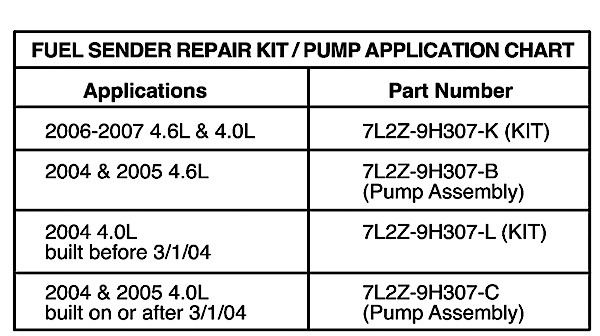
3. Remove the fuel pump assembly from fuel tank. See the chart to determine if a kit (contains a fuel level sensor assembly, a wire harness and heat shrink tube) or fuel pump assembly is required for repair. For vehicles that can be serviced with a kit, go to Step 4. For vehicles that require fuel pump assembly replacement, go to Step 12.
4. Remove the fuel level sensor assembly (sender card/float rod assembly) from the fuel pump assembly.
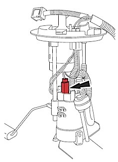
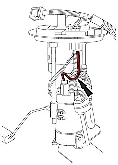
5. Detach the electrical connector from the fuel pump housing (Figure 1).
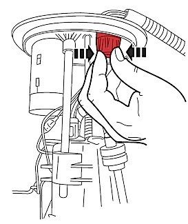
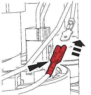
6. Remove the wiring harness from the fuel pump assembly flange by depressing the retaining fingers on the harness connector at bottom of the flange and by pushing upward out of the flange (Figure 2).
7. Install the new wiring harness by feeding the wires through the flange hole and inserting the harness connector into the flange until an audible click is heard. Check for proper retention.
8. Re-attach the electrical connector harness to the fuel pump housing. Prior to making the connection, place one loop in the pump wires away from the convoluted feed tube (Figure 3).
9. Re-attach the signal wire (yellow) on the harness to the signal wire (yellow) on the replacement fuel level sensor assembly (Figure 4).
10. Wrap the ground wire around the signal wire one time and attach the ground wire terminal to the terminal on the fuel level sensor assembly. Check for proper retention.
Note: The ground wire must be wrapped around the signal wire, as described in Step 10, to prevent potential interference with the float rod arm.
11. Re-attach the fuel level sensor assembly to the fuel pump housing, making sure that both the signal wire and the ground wire are routed through the gap between the fuel level sensor assembly and the fuel pump bracket. Torque the fastener at the bottom of the fuel level sensor assembly to 1 Nm (9 lb.-in.).
12. Re-install the fuel pump assembly into the fuel tank.
Note: Take care not to damage/bend the float rod or sender card during installation of the fuel pump assembly.
13. Re-install the fuel tank.
Courtesy of MotoLOGIC® Repair & Diagnostics: www.motoshop.com/motologic