This article will document the P1345 code — CMP Sensor Circuit Malfunction. This is a code that involves the cam sensor input to the PCM. In many situations, one may be tempted to replace the cam sensor right away. This article will attempt to provide a possible plan of attack. I have found through my research that while all of the car manufacturers appear to have similar logic as to how these systems may work, keep in mind you must study each one of them in detail for proper diagnosis and repair.
This month’s diagnostic journey begins with a Mazda product. There are very good websites that provide examples of known-good waveform libraries on various areas of the vehicle. If you are interested in reviewing it, you can contact me at [email protected] and I will provide additional information on it.
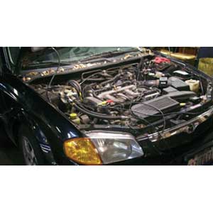
Our subject vehicle is a 2000 Mazda Protégé (Photo 1) with multiple codes stored in memory. The recorded codes are: P0102 (MAF circuit low input); P0103 (MAF circuit high input); and P1345 (CMP circuit malfunction). The engine runs very well at idle, but performance degrades once the engine rpms increase. 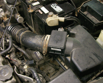
Then the technician cycles the ignition key off and then on again, and restarts the vehicle. It runs as if there isn’t a performance issue. After witnessing this activity, the technician replaced the MAF sensor. This vehicle ran fine for a few days, but was returned to the repair facility with the same complaint later in the week.
The trouble code chart as well as the enabling conditions for each code were then reviewed. The MAF codes could have been caused by a) bad MAF sensor, b) short to ground, c) short to power, d) open circuit or e) wires shorted together.
These five possibilities for this code are electrical strategies that can be used for any circuit. If the circuitry passes these five tests, the electrical 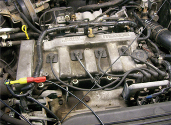 integrity is good; the items that would be left as suspects would be possible poor connections and/or components. Photo 2 shows the new MAF that was replaced at another repair facility.
The last code on the list is P1345 — CMP Circuit Malfunction. The technician then erased all of the stored codes; he wanted to see what trouble codes would reappear as hard failures. The only code that reappeared was the P1345. The technician replaced the cam sensor. See Photo 3. It was interesting to note that this is a two-wire circuit. The cam sensor circuitry was tested end to end with a lab scope. The goal was to witness the cam signal that is sent from the cam sensor and then received by the PCM.
Photo 4 shows two traces on the lab scope, one of them is directly at the cam sensor (red trace) and the 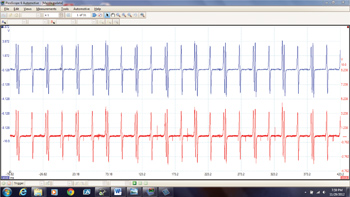 other signal is at the PCM (blue trace). The activity of each pattern is exactly the same. There are no shorts to ground or shorts to voltage, open wires or wires shorted together. The pattern also indicates that the circuitry does not appear to have any poor connections. The vehicle was brake torqued with the transmission gear in reverse. The MAF sensor input on this vehicle is monitored above idle. The code would set once the vehicle engine speed was above idle conditions.
Based on the data collected, it appears that the wiring and connections are good. The cam sensor has good peak-to-peak activity. The last item on the list by deduction is the PCM. The PCM (Photo 5) was replaced and the problem was solved. 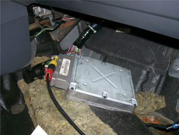 This case is now closed.


