Until relatively recently, engines (and vehicles in general), have primarily operated via mechanical methods. Things we thought would never become digitized have become just that. Such is the case with the mechanical linkage between the gas pedal and the throttle butterfly. A mechanically linked throttle has existed since the very first “motor carriages” were built. Whether the gas pedal connected to the engine with a cable or rods, the link between the driver and the command for power were always a physical one. Now, sophisticated electronic control modules, sensors and actuators have replaced almost all. This system is called Throttle-By-Wire (TBW) or Drive-by-Wire, and it has plenty of advantages, but diagnosing trouble takes a bit more sleuthing than in the old days.
The main reason for the switch to TBW is that it allows the ECM to work in harmony with other engine control systems such as cruise control, traction control, torque management and stability control. Computers have taken over control of the driver’s right foot when it comes to selecting the optimum throttle opening. Computers are especially good in situations where the vehicle may lose traction and require additional aid in the form of stability control. The computer reacts to the situation instead of relying on the driver’s inputs, cutting the throttle to regain traction.
How it Works
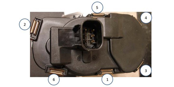
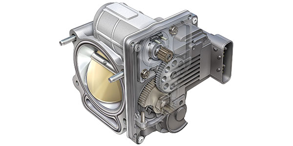
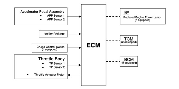
An electric throttle actuator control (TAC) is made of a throttle control motor and two throttle position sensors. When the throttle valve moves, the two throttle position sensors respond with a signal to verify position. These sensors act as potentiometers to convert the throttle valve position into a voltage signal that is sent to the ECM. Besides, these sensors detect the opening and closing speed of the throttle valve and feed the voltage signals to the ECM. The ECM calculates the opening angle of the throttle valve from these signals and then commands the throttle control motor to make the proper throttle valve opening angle in response to the driving conditions. In a perfect world, the system works seamlessly. But when there is something amiss, the system will go into shut down or “limp mode.”
Throttle Body and Accelerator Pedal
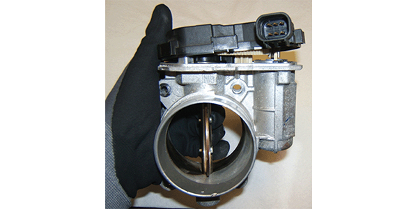
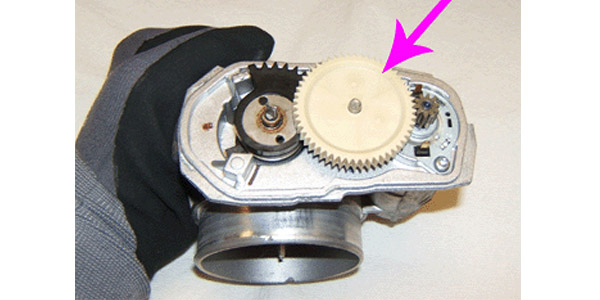
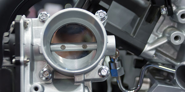
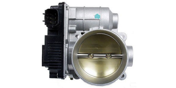
With a few exceptions, the electronic throttle body is very similar to a cable-operated throttle body. One of the most noticeable exceptions is the addition of the throttle actuator control (TAC) motor. This is used to open and close the throttle plate based on commands from the ECM. The TAC turns two reduction gears inside the throttle body that link the drive gear from the motor to the throttle plate shaft. On most systems, idle speed is entirely controlled by throttle plate angle.
Calibration Process
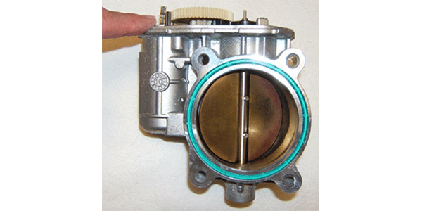
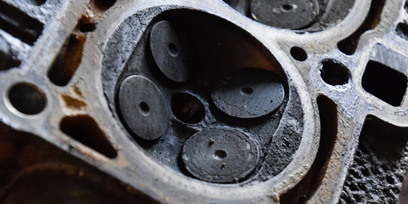
Carbon buildup can accumulate over time around the throttle plate, which the computer responds to by adjusting the home position. If the accumulation occurs gradually, the ECM will learn the new home position on the fly. But if a battery dies or is disconnected to work on the vehicle, the ECM is cleared of its memory and forgets the learned home position. If you replace the throttle body, the ECM continues to use the adaptive settings as if the carbon buildup is still there until it is recalibrated. A relearn procedure is necessary to allow the ECM to relearn the baseline idle. It will eventually learn on its own, but it may take several days to a week of driving. In this time, the engine may experience high and low idle speeds, and possibly rough idle.
The following is an example of a throttle body relearn procedure from GM:
1. Start the engine and let it idle for three minutes in park. The engine may idle higher than usual in this time.
2. After a few minutes, turn the engine off and leave it off for one minute.
3. Start the engine again, letting it idle for three more minutes. During the run time, a check engine light may come on. If you get throttle body related codes, go ahead and clear the codes.
4. If the idle speed continues to be high, drive the vehicle at speeds over 44 mph, performing multiple acceleration and deceleration cycles. Then repeat step three one last time.
Some scan tools can also perform the relearn procedure, but they are all mostly the same. The process is set up to make a baseline and then fill in the blanks from closed throttle to wide-open-throttle (WOT).
Diagnostics
Most of the faults that occur in TBW systems relate to pedal or throttle position sensors that may wear out, skip or emit erratic signals. Throttle body motor failures and electrical problems, such as loose or corroded, wiring connectors are also common.
A scan tool, or at the very least a code reader, is necessary for a proper TBW diagnosis. OBD II trouble codes for accelerator pedal position (APP) sensor faults include P0120 – P0124, P0220 – P0229, plus any OEM enhanced P1 or P2 series codes for a specific application.
Any fault that occur in the motor on the throttle body will be detected by the feedback signals from the throttle position sensors. OBD II codes for this kind of problem include P0638 and P0639, plus any OEM enhanced codes for the application.
The TBW system also monitors the throttle position sensors on the throttle body. A fault here can set any of the same OBD II codes just listed for the pedal position sensor, or OEM enhanced P1 or P2 series codes for that specific vehicle.
Diagnosis involves reading the fault codes to determine the circuit that is experiencing the problem. Then you should check the voltage or resistance of the pedal or throttle position sensors with a DVOM, or check the operation of the throttle control motor by visually observing the throttle when the gas pedal is depressed, or check the duty cycle from the ECM using a scan tool.
When the fault has been identified, the faulty part can then be replaced. It is better to run through these diagnostics than to unnecessarily replace components, such as a throttle body or ECM, if the problem was merely carbon buildup. Then you can clear the buildup, and hopefully, everything will work correctly again.
SIDEBAR
 Before connecting a scan tool, do a visual inspection of the TBW wire harness and look for signs of rubbing, chaffing or exposed wires. Make sure the harness is secure and routed correctly to eliminate the chaffing condition. Repair any problems. Use a scan tool to monitor Throttle Position Sensor (TPS) 1 and TPS 2 voltage while fully depressing and releasing the accelerator pedal. TPS voltages should move opposite of each other in smooth increments within a normal voltage range (0.35-5 volts). If the range is not correct for each sensor and the TPS 5-volt and low reference voltages are correct, replace the throttle body assembly or replace the throttle body cover where applicable. If no problem is found, clean the throttle body, clear the codes and perform the idle relearn procedure.