 Every once in a while a vehicle comes to the shop with a driveability concern and no codes available to aid in the diagnosis. As techs, we use our knowledge and all the tools we have available to try to diagnose the vehicle correctly the first time. Unfortunately, sometimes, we aren’t able to find out exactly what the root cause of the concern is, and the vehicle may leave the shop not repaired and then come back another day as the concern persists or worsens — or not return at all if the customer loses faith with our abilities.
This article will try to help you repair driveability concerns the first time and avoid those comebacks. This month, we’ll focus on a loss-of-power concern on vehicles with an electric return-type fuel system.
During high-calculated loads and on steep grades, vehicles with an electric return-type fuel system may act as if they’re running out of fuel, and depending on geographical locations, this may happen occasionally or worsen quickly. During all other driving conditions, these vehicles run and perform fine.
Pump Up the Volume
While the fuel system may be able to maintain the correct fuel pressure during most driving conditions, the volume, however, can be low and even close to zero and still run. Volume can be influenced by many different factors, so a full analysis must be completed.
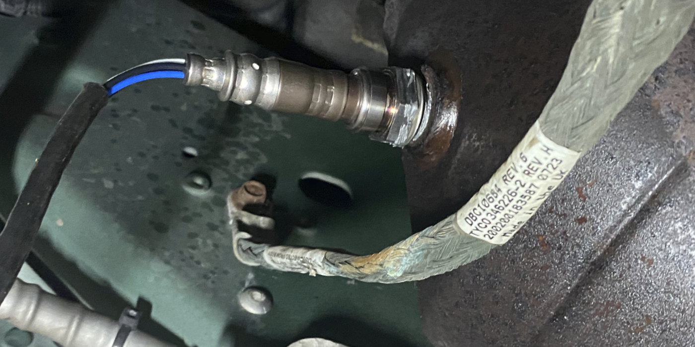
Short- and long-term fuel trims (STFT and LTFT) are the adjustments made by the PCM/ECM to maintain the ideal 14.7:1 air/fuel ratio. Total fuel trims are the combination of STFT and LTFT added together. Total fuel trims may be seen on the plus side where PCM/ECM is attempting to richen the fuel mixture by adding fuel to counterbalance an apparent lean condition; however, the condition may not be extreme enough to set a DTC. Checking for low volume can be seen while driving the vehicle and watching the fuel trims or pressure when accelerating. STFT will increase to the plus side and fuel pressure may drop below the manufacturer’s specifications. Another indication of being lean is if the front oxygen sensor(s)’ voltage(s) do not increase to maximum voltage quickly on acceleration. But this still may not be conclusive evidence of the exact concern. Depending on the severity and vehicle, you may be lucky enough to have lean codes P0171 and P0174 set in memory to help with diagnosing.
Fuel System Breakdown
Fuel systems can be broken down into two types: fuel return and returnless. While we’re focusing mostly on return-type systems in this article, returnless-type systems are becoming more popular today due to evaporative emissions and gasoline direct-injected systems.
Return-Type Fuel Systems
Fuel flow is measured on a return-type fuel system with the continuous flow of fuel from the tank to the fuel rail and excess fuel (not used) flowing back to the fuel tank via the fuel rail pressure regulator. Volume is very important on return systems with electric fuel pumps to make sure we get the correct amount of fuel delivered to the fuel injectors. 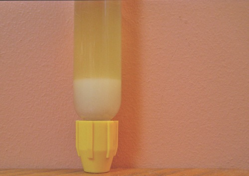
Before we go any further, now is a good time to check for a good supply of clean voltage. Battery/ charging voltage has tremendous influence on the amount of fuel that flows though the fuel system itself. If the correct voltage is not maintained, the fuel pump may not be able to deliver the correct amount of volume. Remember, the voltage is the pressure or push, so the higher the voltage, the more of a push and the higher the current flow. Be sure to check your charging system before continuing to check the fuel system itself when considering volume. During testing we’ve found that even a one-volt difference can change volume by over one-third.
For example, fuel volume at 14.2 volts is 0.5 gallons per minute (gpm) (1.9 liters per minute [lpm]) if the voltage were to be lowered to 13.2 volts, the volume will be lowered to around 0.3 gpm. Keep in mind, the days of a vehicle not cranking from a dead/weak battery are over — batteries do not fail as they did in the past. With computerization and engine control systems today, the engine can start quickly with a minimum amount of voltage. Many concerns associated with battery and voltage can go unnoticed if the vehicle starts and/or cranks quickly. Many customers still assume if the vehicle cranks, then the battery must still be good.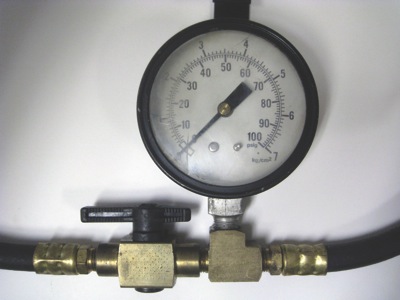
Our next step is to check the fuel quality for contamination, most commonly alcohol. An alcohol fuel test kit can be purchased or you can make your own with a graduated cylinder or bottle. Combine one part water to five parts gasoline and shake for 30 seconds, let it sit for approximately 10 minutes for the alcohol to combine with the water. Next, subtract the initial amount of water added from the level of clear liquid and multiply the increased amount by 10 for the alcohol percentage.
Alcohol can drive fuel trims to the positive side due to the high oxygen content and the lack of British Thermal Units (BTUs). Flex fuel vehicles have the ability to adjust for increased alcohol; however, if the vehicle is not a flex fuel vehicle, fuel trims can be high, with the system continually trying to richen the mixture. Checking for alcohol is fairly easy, as seen in Figure 1, and should be done with all driveability concerns, lean codes and catalyst codes.
During my career of teaching, I’ve found that most technicians or shops use tools to check electric return-type fuel systems that may result in incorrect data. Most shops have a fuel gauge that connects to the rail with a teed line and a button or valve to drain fuel into a container, see Figure 2. When running the engine, the valve is opened and fuel is delivered into the measured container. Unfortunately, this fuel measurement tool design doesn’t work very well with electric fuel systems to check volume. When the fuel system is opened to the atmosphere, the pressure drops. This allows the fuel pump to spin faster, delivering more fuel than the actual volume into the measure container, appearing to have plenty of fuel, and giving inaccurate results. Unfortunately, this can lead to test results appearing as if the volume is correct and possibly missing a correct diagnosis. From this point, the technician may move on to diagnose other systems or worse, 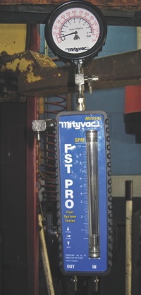 replace parts trying to rectify the concern. (This is the vehicle you give back to the customer on a late Friday afternoon knowing right well it isn’t fixed, telling them to try it and see if it is any better — at least you’ll have a peaceful weekend!)
When checking the volume correctly in an electric return-type fuel system, it is recommend to use a closed loop fuel system flow tester, see Figure 3. These are typically incorporated with a fuel pressure gauge to check pressure and volume at the same time. These testers have a flow gauge with a float in a clear tube, the float moves to a measured level inside the tube when fuel is 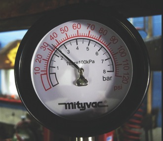 flowing. Fuel volume should be consistent and will not change with throttle opening, engine load or temperature. This allows an accurate test in the shop, eliminating the need of a road test. The average fuel volume is around 0.5 gpm, but you may need to check an aftermarket source if the OE doesn’t supply volume specification. A rule of thumb is about 0.5 gpm or higher.
While testing a Ford Taurus, I found the fuel pressure of 35 psi (Figure 4) was within specifications of 30-45 psi Key On Engine Off (KOEO). When checking the flow, it was 0.24 gpm — far below the minimum needed of 0.5 gpm (Figure 5). 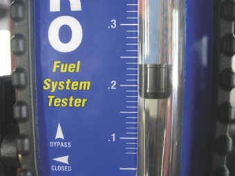
Quick calculation: a fuel pump that delivers 0.5 gpm will pump 30 gallons per hour (gph). A vehicle getting 30 miles to the gallon will use 2 gallons of fuel per hour when driving at 60 mph.
In the case of the Taurus, 28 gallons of fuel are being returned to the fuel tank per hour. There would have to be a 28-gallon-per-hour decrease in fuel volume before a change in pressure would be seen.
Another benefit of this fuel system tester is the clear tube that gives a view of the fuel to check for contamination and/or air bubbles in the fuel, see Figure 6. 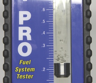
Volume should be a fairly consistent; somewhere between 0.5 to 0.7 gpm. Always refer to manufacturer’s specifications for correct fuel pressure and volume. Check the fuel pump relief valve pressure by deadheading the pump; some fuel system tools have a valve that can be turned to block the fuel line for maximum pressure, see Figure 7. In-tank fuel pumps typically have a relief valve to protect the system in case of a fuel line blockage, this valve relieves fuel pressure around 90 psi. This will see if the pump is capable of building pressure high enough to open the relief valve and if the valve is working. Also, it’s a good idea to check the “check valve” — the check valve holds fuel in the fuel lines and rail(s) to maintain pressure when the engine is turned off. If the check valve is bad, the vehicle may exhibit hard starting or vapor lock (fuel boiling in the rail on hot soaks) — remember an increase in pressure increases the boiling point. This is most likely to occur in the spring when switching from winter to summer fuels; winter fuel’s boiling point is about 50° less than summer fuel.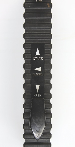
Returnless-Type System Checks
Fuel system testers are useful on returnless-type systems as well to check for relief and check valves along with contamination and aeration. Returnless systems have very little if no measureable flow when measured with a closed-loop flow gauge. Fuel pressure also may not be very helpful when checking using a mechanical fuel pressure gauge; most specifications refer to the Fuel Rail Pressure (FRP) sensor reading from scan tool data, which is referenced from manifold vacuum. Mechanical gauge pressure is referenced from atmospheric pressure and will not match the FRP sensor reading.
Also, don’t overlook engine vacuum and back pressure. Remember to research the specific vehicle you’re working on. Some vehicles use variable fuel pump systems, which change fuel pressure as needed during different driving conditions. Some may be mechanical or electronically regulated and will be tested differently. To help complicate things, some vehicles combine a return-type and returnless system into one (running loses fuel supply) changing back and forth as load and rpms change.
Using tools and equipment to provide correct information and data for accurate diagnosing is important to repair the vehicle correctly the first time. Always remember your repair is only as good as your knowledge, tools and parts when diagnosing and repairing a vehicle. An educated technician does in the beginning what an uneducated technician does in the end.