Utilizing electronically controlled wastegates and bypass valves
With the ability to increase fuel economy by up to 20% on gas vehicles and up to 40% on diesel vehicles, manufacturers have resorted to turbochargers to compensate for lowered engine displacement. Additionally, the improvements on turbocharging technology have increased the number of turbocharged vehicles on American roads. Some turbocharger manufacturers have even projected the number of turbocharged vehicles in the U.S. to quadruple in the next five years. To prepare technicians for the influx of the latest turbocharged vehicles, this article will cover the basic operation of the turbocharging system, electronically controlled wastegates and bypass valves, and feature a small segment on service/diagnostics.
System Parts
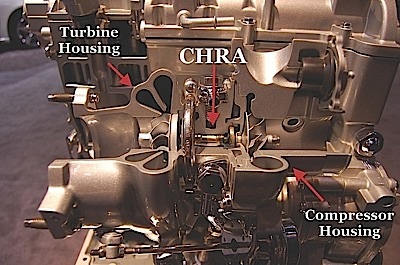
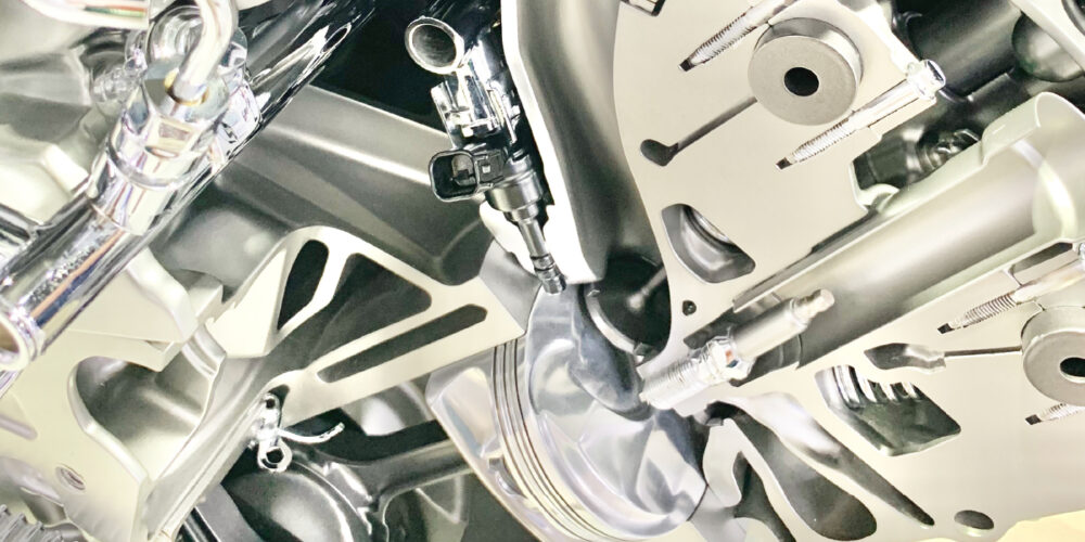
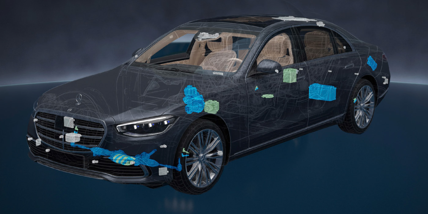
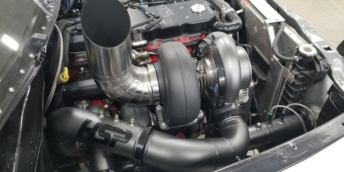
The turbocharger consists of three main sections: compressor housing, center housing rotating assembly (CHRA) and turbine housing (see Figure 1). The compressor housing, also known as the cold side, houses the compressor wheel and is attached to the CHRA and the intake plenum. The CHRA section consists of the compressor wheel, turbine shaft, turbine wheel, bearings, and oil and coolant passageways. The CHRA is also referred to as the bearing housing. Lastly, the turbine housing, also known as the hot side, contains the turbine wheel and, on most applications, an integrated wastegate.
Naturally, the temperature of the air will increase when compressed. Therefore, an intercooler is used to cool the air discharged from the compressor and increase power output. This radiator type component can be water-to-air, much like a radiator, or air-to-air where only ambient air passing over the fins cools the air passing through the intercooler. There are several locations where the intercooler can be mounted: front-mount intercoolers (FMIC) are located in front of the radiator, top-mount intercoolers (TMIC) are located on top of the engine, and side-mount intercoolers are usually located inside the bumper (see Figure 2).
Although forcing more air into the cylinders increases the volumetric efficiency of the engine and desirably increases its power, there needs to be a way to control boost pressure. Since the turbocharger utilizes heat energy from the exhaust to produce boost and, more boost pressure produces more heat, a catastrophic chain reaction can occur if not controlled. Excessive boost can cause major turbo and engine damage. Conversely, a deficiency in boost pressure will decrease the power output of the engine. Most systems utilize a wastegate and/or a bypass valve to control the system.
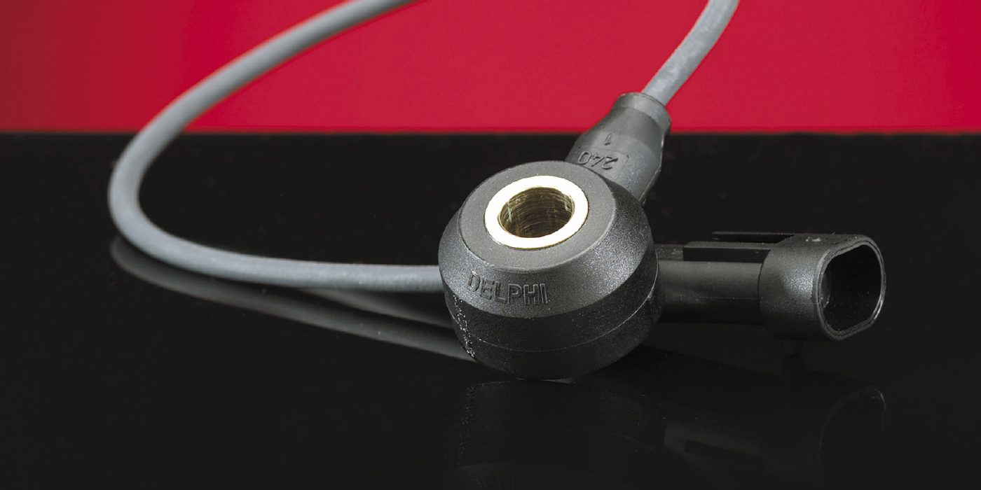
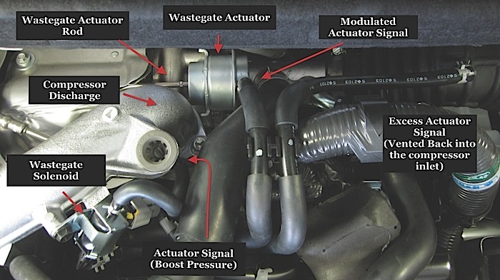
Wastegates are used to control boost pressure by redirecting the exhaust gases around the turbine wheel to bypass or maintain flow to the turbo. It utilizes a diaphragm attached to an actuator rod to open and close a valve. As shown in Figure 3, most OEM wastegates are integrated into the turbo, but some aftermarket applications utilize a remote design to enable the use of a larger diaphragm and better materials. The wastegate is controlled by the amount of pressure the turbo is creating. This pressure, usually derived from the intake manifold or compressor discharge, is referred to as the wastegate actuator signal. The valve opens once the wastegate actuator signal overcomes the diaphragm spring. Most OEM systems will release the pressure back into the 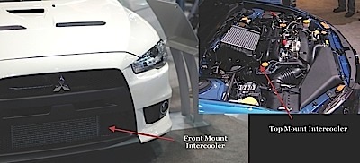 exhaust system for emissions purposes, but some performance vehicles release the pressure to the atmosphere.
While the wastegate protects the vehicle from producing too much boost, the bypass and pressure release valves, sometimes known as a blow off valve (BOV) or surge valve, are designed to release or displace boost pressure when the throttle is closed (Figure 3). The unnecessary boost pressure is directed back into the compressor inlet after the mass air flow (MAF) sensor or out to the atmosphere. Directing the flow after the MAF prevents the system from running too rich when the throttle is abruptly closed. Unlike the wastegate, both the bypass and pressure release valves are controlled by manifold vacuum. In addition, boost pressure assists in opening the valve by pushing while manifold vacuum pulls against the spring tension.
Electronically Controlled Wastegate and Bypass Valves
On late-model unmodified vehicles, the wastegate and bypass valves are electronically controlled by the power control module (PCM) to increase efficiency and horsepower. Several engine sensors influence these electronically controlled systems: manifold absolute pressure sensor (MAP), throttle inlet pressure sensor (TIP), knock sensor (KS), throttle position sensor (TPS) and MAF. Some systems are designed with multiple pressure sensors to effectively control the turbocharger.
There are two means to electronically control the wastegate. One utilizes a solenoid, usually referred to as the wastegate solenoid, which is duty-cycled to prevent or redirect the actuator signal (boost pressure) going to the actuator diaphragm. Controlling the wastegate electronically and not relying solely on the mechanical pressure of a spring prevents the wastegate from prematurely cracking open as boost pressure rises, allowing the system to produce an optimum amount of boost without endangering the engine.
The other means utilizes an electric motor to directly drive the wastegate actuator rod. Being electrically driven versus pneumatically driven allows the wastegate to open without boost pressure. This increases the speed of producing maximum boost pressure by keeping the valve closed until needed to be opened, and allows the system to increase fuel efficiency by opening the valve to decrease pumping loss when boost is not needed. Additionally, the wastegate can be opened during cold starts to decrease catalytic converter light-off time.
Vehicles equipped with an electronically controlled bypass valve also utilize the PCM to activate a solenoid, sometimes referred to as the bypass valve or surge valve solenoid. Unlike the wastegate solenoid, the bypass valve solenoid is duty-cycled to control manifold vacuum. The bypass valve will not open until manifold vacuum is present at the valve’s diaphragm.