Current Ramping – Ignition Coil
Regardless of design configuration, the role of the ignition coil is to multiply battery voltage into high voltage, which will provide the necessary spark. Following Ohm’s law for the conversion of volts to amperes, oil-filled coils generally require from 3 to 5 amperes of primary current to produce 20,000-30,000 volts of secondary current. Modern E-core and COP (coil-over-plug) ignitions require as much as 7 amperes of primary current in order to produce 30,000-60,000 volts of spark output. The end result is the coil producing enough voltage to arc across a spark plug gap of 0.035 in. to 0.060 in. u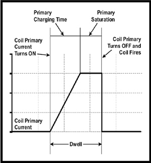 nder cylinder pressures as high as several hundred pounds per square inch.
Although the resistance test is not a definitive measure of a coil’s electrical integrity, a coil should be replaced if the resistance values don’t fall within specifications. 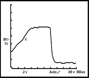
The diversity of modern ignition coil designs has made ignition oscilloscope analysis more difficult because many ignition coil waveforms deviate from the conventional norm. Consequently, oscilloscope diagnosis shouldn’t be considered a definitive test of ignition coil condition unless it can be compared with a known-good waveform. See Fig. 1 and Fig. 2
On the other hand, using a low-amperage current probe to measure the current “ramp” through the primary ignition circuit is perhaps the most definitive method of determining the electrical integrity of the coil and the quality of the triggering action. Many defective ignition coils, for example, will pass a resistance test, but fail a current ramp test. When testing multiple coil systems, the current ramp gives an excellent comparison of current flow through each coil in the ignition system and usually helps the technician arrive at a more accurate diagnostic conclusion.
Visit http://am.delphi.com/products/training to learn more about this training course or other Delphi training.