Some 1995-2004 Chevrolet Astro Van and GMC Safari owners may complain about a “boom” noise inside the vehicle while driving at speeds between 60-65 mph. This condition is most noticeable from behind the driver’s seat. The noise may result from an engine-firing harmonic, which becomes noticeable at torque converter clutch (TCC) lock-up. A new rear leaf spring damper kit (one per spring) has been developed, to be used in conjunction with a pinion nose damper tuned to 86 Hertz (Hz) to reduce the resultant noise level. The procedures and parts described in this Tech Tip should help resolve the condition.
Review safety procedures in ALLDATA Repair before beginning.
NOTE: AFFECTED VEHICLES MAY REQUIRE THE INSTALLATION OF THE PINION NOSE DAMPER, THE SPRING DAMPERS, OR BOTH. THE INSTALLATION OF EITHER OF THESE DAMPERS IS AT THE DISCRETION OF THE TECHNICIAN FOR BEST RESULTS.
Important: Installation of these dampers will not totally eliminate the boom noise. The boom noise may only be reduced to a more acceptable level. There may be other boom noises, such as body or exhaust, associated with the vehicle and this fix may either diminish or enhance the noise. These other noises should be addressed prior to the correction for the TCC boom dampener being installed.
Pinion Nose Damper Installation Procedure
Use Damper Kit, Rr. Axle Vib., P/N 15006567, for this procedure.
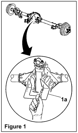 1. Place the template (1a), P/N 15005879, on the bottom surface of the triangular flanged portion of the rear axle (Figure 1).
2. Mark the hole locations.
3.Using a pin punch (2a), mark the center location of the holes (Figure 2).
4. Drill a 0.44 in. (11 mm) diameter hole in two places.
5. Clean out the holes, including the top and bottom surface of the axle.
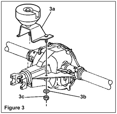
6. Install the rear axle pinion nose damper (3a), P/N 15005880 (Figure 3).
7. Install the rear axle pinion nose damper washers (3b), P/N 15614758, and the nuts (3c), P/N 11516072. Tighten each nut to 27-39 lb. ft. (37-53 N.m).
8. Rotate the driveshaft in order to verify that there is no contact between the driveshaft and the pinion nose damper.
9. Test drive the vehicle. Inspect for contact between the driveshaft and the damper.
Rear Leaf Spring Damper Installation Procedure
Use Damper Kit, Rear Spring Vib., P/N 15042486, for this procedure.
1. Raise the vehicle. Support the rear axle using factory and/or industry standard approved practices.
2. Remove the leaf spring using factory and/or industry standard approved practices.
3. Locate the rear spring clip closest to the shackle. This clip maintains the alignment of the rear spring plates #1 and #2.
Note: Do not damage the top surfaces of the #1 and #2 spring plates. Damage may cause premature spring breakage.
4. Insert a wood wedge, no metal or sharp objects, between rear 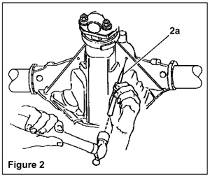 spring plates #1 and #2, located forward of the clip. Allow enough clearance to work around. This should maximize the gap between spring plates #1 and #2.
5. Grind off or, using a 0.44 in. (11 mm) drill bit, drill out the rivet head holding the clip to the #2 spring plate.
6. Remove the clip and the plastic clip liner from the spring assembly. Discard the spring clip only.
7. Knock out any remaining rivet residue from spring plate #2.
8. Insert the stud bolt (4b), P/N 15042491, from the top of spring plate #2 (4c) so that the bolt head sits into the hole’s counter sink (Figure 4).
9. Place the spring clip (4a), P/N 15042492, over the stud so that the clip is in a similar position as the original clip removed previously. Do not close the clip at this time.
10. Install the damper (4h), P/N 15042487, onto the stud. Install the
 damper completely onto the stud so that the clip is securely trapped between the #2 spring plate (bottom) and the damper inner sleeve. Tighten the damper to 22 lb. ft. (30 N.m) while holding the stud.
11. Install the jam nut (4f), P/N 11508189, onto the stud until the nut is against the inner sleeve of the damper. Tighten the nut to 22 lb. ft. (30 N.m).
Note: Do not break the clip liner or damage the top surface of the #1 spring plate.
12. Install the plastic clip liner in the same orientation as when removed. The bolt head may stick up above the top surface of the spring plate.
13. Remove the wood wedge.
14. Using a press or a vise, close the clip to the same position as the removed clip. The maximum width of the installed clip is 3.6 in. (91.5 mm) and the maximum height is 1.8 in. (46.5 mm). This ensures proper clearance to the body rails.
15. Install the leaf spring onto the vehicle using factory and/or 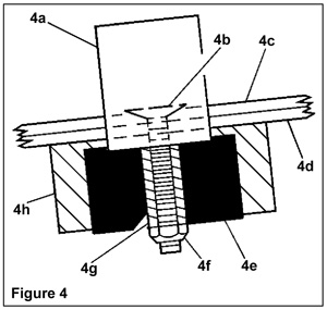 industry standard approved practices.
16. Repeat steps 2-15 for the other spring and road test to verify repair.
NOTE: This Repair/Service Procedure is excerpted from a Technical Service Bulletin published by the vehicle manufacturer, and is intended for use by trained, professional technicians with the knowledge, tools and equipment to do the job properly and safely. It is recommended that this procedure not be performed by “do-it-yourselfers.”
Ed Dorowski has 19 years of Domestic and Import dealership and independent shop experience as a service consultant, ASE Certified Master Technician, Nissan Certified Master Technician, & California Smog Test & Repair Technician. Jeff Webster has 20 years of experience as a writer/editor.
Courtesy ALLDATA LLC.