This bulletin provides information related to the Throttle Position Sensor (TPS) for Sorento and Sedona models. Some Sorento and Sedona vehicles may exhibit diagnostic trouble codes P0121 and/or P1121. This condition mainly occurs in high ambient or desert areas, and can be related to the occasional increase in contact resistance due to excessive wear of the inner elements of the TPS. This bulletin describes the proper service and adjustment procedure for replacing the TPS.
Note: This service bulletin applies only to vehicles equipped with 3.5L engine.
Effective Vehicle Information:
2003-’06 Sorento 3.5L
2002-’05 Sedona 3.5L
Parts Information:
Throttle Position Sensor:
Old Part No. New Part No.
35102 39000 35102 39000FFF
Service Procedure:
Replacement Procedure:
1. Turn off the ignition. Remove the engine cover and disconnect the electrical connector from the TPS.
2. Remove the two retaining screws from the TPS and remove from the throttle body. See Fig. 1. 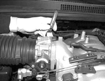
3. Install the new TPS to the throttle body. Install the retaining screws and lightly hand-tighten. (Adjustment will be required.) Re-install the electrical connector to the TPS.
4. Install the Global Diagnostic System.
a. Select “System Option.”
b. Select “Idle RPM Adjust Mode.”
c. Apply the parking brake.
5. Select the Neutral position and place the engine in the idle condition with the A/C off.
*Note: During this test, the MIL will be on.
6. Remove the rubber plug (see Fig. 2) and adjust it using instructions provided on screen. Set base idle between 800-900 rpm. 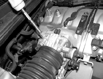
*Note: Re-install the removed rubber plug when idle speed adjustment is complete.
Adjust the TPS: (see Fig. 3) 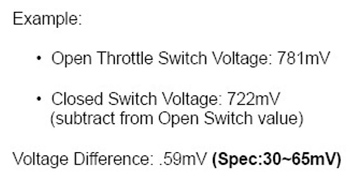
7. Using the GDS scan tool, monitor current data using two parameters:
– Closed Throttle Position Switch
– Throttle Position Voltage Value
8. Open the throttle by hand very slowly until the idle switch status switches to off. See Fig. 4. 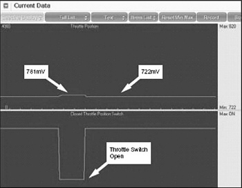
Note the TPS voltage value.
Voltage: _______________
9. Close the throttle and record the TPS voltage. See Fig. 5. 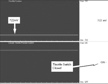
Voltage: ____________
Closed throttle voltage should be 30-65 mV less than the voltage noted in step 8.
Adjust the TPS and repeat the test as required.
10. Tighten the TPS screws as required. Torque: 12-18 in.-lbs. Verify switching of the throttle switch with the throttle plate movement.
11. Install the engine cover.
12. Clear any stored DTCs that may have set during the service procedure. Remove the GDS tool from the vehicle.
Courtesy of Mitchell 1.