There may be no way to know exactly how many, but way too many starters are replaced each year because of misdiagnosis. Are you unnecessarily replacing good rotating electrical components due to a mistake? Here are some top tips for diagnosing starters on late-model vehicles.
CHECK THE INPUTS
A no-crank condition might be caused by a bad ignition switch, an open park/neutral safety switch or an open clutch pedal safety switch. It could even be caused by the immobilizer or security system due to a malfunctioning key fob. Use a scan tool to confirm the inputs into the ECM.
CHECK THE WIRING DIAGRAM
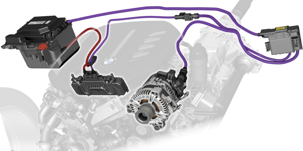
On late-model vehicles, the starter might not be wired directly to the ignition tumbler or start button. The command to crank the engine might go through two or more modules before it energizes the control side of a relay that actuates the solenoid on the starter. This is why looking up the wiring diagram is critical to your diagnostic strategy on late-model vehicles.
DO NOT SWAP RELAYS
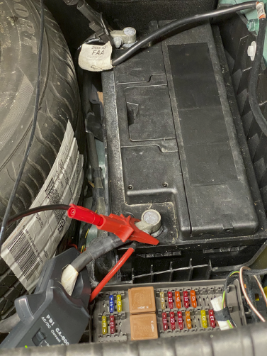
It is an old mechanic’s trick to swap relays around in the fuse box to see if it fixes the no-crank situation. This can damage the ECM or power management module if the relay or starter circuit is short to ground or power. The module typically contains a transistorized driver on the main circuit board that is connected to the control side of the relay. If you swap relays, you could damage the relay or module. This method can also give inconclusive results. What is the best approach? Use a scan tool that can bi-directionally control the starter relay.
VOLTAGE DROP STILL WORKS, BUT IN A DIFFERENT WAY…
Most late-model vehicles have anywhere between three to five computer networks. The modules on these networks communicate with each other by switching power on and off in specific patterns. The voltages typically toggle between zero to seven volts.

If the battery is weak or the starter is drawing too much current, the system voltage could drop below seven volts and interrupt the networks in the vehicle. When this happens, the ECM will shut down, injectors will not spray, and ignition coils will not fire.
Testing for this can be performed with a scope recording system voltage or a meter set using the min/max function. Also, codes for loss of communication and system voltage will be set in multiple modules.