This article is the third in a series beginning with the June 2011 and December 2011.
Pulling Codes articles. The overall goal is to show four different techniques that are currently being used in the field.
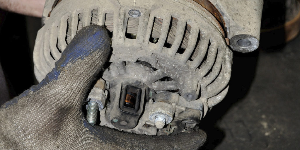
In the first two articles, we looked at cranking compression and tailpipe analysis. We will now explore in-cylinder analysis. In order to have an understanding of this concept, one must envision the four-stroke cycle at the time the plug fires as a reference. This denotes the end of our compression stroke, and the beginning of the power stroke for that cylinder. (Keep in mind that this is just a visual reference, other factors are added in.) The piston then travels 180 degrees and, in theory, we are now at the end of the power stroke or the beginning of the exhaust stroke for that cylinder. The piston travels an additional 180 degrees to reach the end of the exhaust stroke or beginning of the intake stroke. The piston travels an additional 180 degrees of travel to reach the beginning of the compression stroke. A final 180 degrees of travel will place us at the same location we started. This yields a total of 720 degrees of crankshaft rotation. I use a device called a pressure transducer that I place in the cylinder after removing the spark plug.
This analysis provides the most interesting of concepts; it allows the observer to verify cam timing arrangement before any teardown is attempted. The concept is an overall simple one in reference to the four-stroke cycle. If you’re interested in learning more about this tool, you can go to www.wavehook.com and click on the tab labeled “transducers.” I’ve found this tool to be the most valuable for engine mechanical analysis.
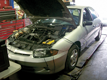
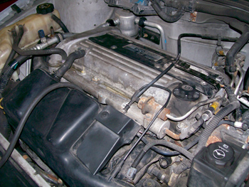
Let’s begin our evaluation. Our subject vehicle for this Pulling Codes case is a 2003 Chevrolet Cavalier with the 2.2L Ecotec engine. Before I arrived at the shop, I received some data on the vehicle: the fuel trims were negative, vacuum was low (16” Hg) and there was poor idle quality. They also stated that the engine appeared to misfire on all four cylinders. At the shop, I quickly reviewed the scan data, which showed multiple misfire activity on all four cylinders. My first thought was to check cam timing, but my friend at the shop strongly stated that it checked out fine on teardown. 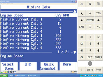
In an effort to gather additional data, I checked the fuel and ignition systems. Both areas checked out fine. I decided that cam timing should be looked at again. I placed the transducer in one of the cylinders and analyzed the pattern. See Figure 1. 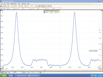
The two labscope patterns (Figures 2a and 2b) show the activity we witnessed while the engine was running at idle. I will give a play-by-play analysis of our interpretation. Let’s start with Figure 2a, this is the pattern obtained in reference to pressure in the cylinder. It’s difficult to evaluate this pattern without placing a template over it, so Figure 2b shows the template over the pattern. 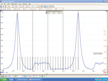
A review of the pattern with the template in place implies that cam timing is off. A closer inspection indicates that cam timing is retarded. The exhaust valve opening is too late in reference to specifications for this engine family; this is referred to as EVO. I then reviewed service information to obtain additional data on this. Figures 3a, 3b and 3c show the proper arrangements for cam timing.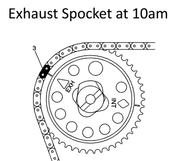
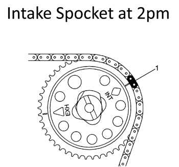

I asked that the engine cover be disassembled again as I felt that based on my pattern, cam timing was off. The number of teeth on the cam totaled to 46. This equates to 15.65 crank degrees per tooth. The exhaust valve is opening about 30 degrees too late, which equates to two cam gear teeth being offset. It was interesting what we saw once it was taken apart for review. Figure 4 shows the proper arrangement for all three gears, which is: exhaust cam gear at 10 a.m., intake cam gear at 2 p.m., crank gear at 5 p.m. The actual arrangement that was noted was: exhaust cam gear at 11 a.m., intake cam gear at 3 p.m. and the crank gear at 6 p.m. 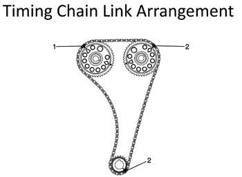
A colored link was used to mark the arrangements for each gear. The links were shifted by one to get the arrangement as indicated in service information. The fuel trims returned to normal, vacuum levels were now high and steady (20” Hg), idle quality was now acceptable.
This wasn’t a difficult one to diagnose, but it does bring forth the fact that new techniques can and will yield conclusive results. This Pulling Codes case is now closed. If you would like to offer any comments on this, please e-mail me at [email protected].