Solving temperature-related, no-code intermittent failures can be a frustrating experience for the diagnostic technician because the exact level of heat or cold needed to trigger the failure is often hard to duplicate. It’s also important to keep in mind that all electronic vehicle components are exposed to temperature extremes and thus are vulnerable to temperature-related failures.
Early in my electronics diagnostics career I had to deal with a 1980s-model Nissan pickup that wouldn’t start when ambient air temperatures dipped below 20° F. One shop had already replaced the engine coolant temperature sensor in an effort to solve the problem and, because no data stream information was available on that model of Nissan, I was left with pin-testing individual sensors in freezing temperatures. Unfortunately, the vehicle would start as soon as the ambient air temperature rose above 20° F, so the diagnostic process would be put on hold until colder weather prevailed. Why 20° F had become the threshold temperature needed to trigger the failure, I can’t say because I could rarely duplicate the required temperature condition. In this case, the temperature-related failure might have been caused by a faulty winding in an ignition coil or solder joint in the circuit board of a computer, ignition module or air flow sensor.
The Stalling Nissan Quest
This month, I’ll present two case studies that illustrate how data collection and logical analysis can help locate the failure. The first step in solving intermittents is to gather as much information from the owner as possible. Unfortunately, some customer descriptions of the failure provide little guidance or information. Case in point is a 1996 Nissan Quest van with 140,000 miles on the odometer that, according to the owner, “loses power and sometimes stalls on a warm day.”
The situation was complicated by the customer having loaned the van to a friend living in a city 125 miles away. The friend drove the van on short trips on a metro-area commute and seldom experienced the problem. The owner, however, became alarmed by an intermittent loss of power and stalling problem when he brought the van home on an over-the-mountain trip home in warm fall weather.
The Usual Suspects
A weak fuel delivery system tops the list of my “usual” suspects for any temperature-related stalling and loss-of-power complaint. On any vehicle like this Nissan that’s equipped with an external fuel pressure regulator, the return fuel heats the remaining fuel in the tank. On a warm day, the fuel tank temperature can easily exceed 100° F, which will aggravate vapor locking tendencies on poorly designed fuel pumps and may also cause marginal fuel pumps to fall short of their fuel delivery requirements.
Fortunately, testing the fuel pump is easy on this Nissan because the fuel pump fuse is located in the underhood fuse box next to the front radiator core support. Tapping into the fuel line for a pressure and volume test is also easy because the fuel filter is clamped to a neoprene fuel line, which eases the task of removal and adaptation. Replacing the fuse with a fused jumper wire allows the current draw to be measured with an inductive probe attached to a multimeter. Better yet, the waveform pattern generated by the fuel pump can be displayed from the same fuse location.
Because the owner eventually wanted to sell the vehicle, it was left with me as a spare-time project for the winter months. As you might suspect, no trouble codes were stored in the diagnostic memory. The engine’s thermostat was stuck open, which prevented enabling criteria for specific trouble codes from being met. After replacing the thermostat and test-driving the vehicle, the engine ran perfectly with no trouble codes stored. Of course, I was test-driving the vehicle in the cold grip of winter and not on the warm fall day that the owner had described.
Finding the Failure Pattern
Here again is one of the reasons temperature-related diagnostics can’t be performed on a scheduled basis. Many shops simply duck the issue by performing a short test-drive and reporting “no problem found” (NPF) on the repair order. I certainly understand their actions because many hours and days can be wasted pursuing a problem that doesn’t exist until a temperature extreme presents itself.
 But, with the Nissan, I found time to begin diagnosing the problem on a warm mid-winter day when I could park the vehicle outdoors, leave the shop door open, attach a scope and fuel pump tester, and wait for the failure to occur. The fuel pump tested perfectly, with the amperage draw rising from about 3 amps to 4 as the fuel tank temperature increased. But, after the engine ran about an hour, it began to stumble as if it were running on three of its six cylinders. Although the fuel pressure was on specification, the engine refused to accelerate and finally died altogether. A quick check revealed a curiously random, tenuous spark at the coil terminal. Unfortunately, I was called to the phone for a few minutes and, when I returned, the engine started and ran flawlessly for yet another hour before the symptoms reappeared!
 For the first time since I had taken on the job, I had established a failure pattern on the vehicle. First, the engine had to run at least an hour before the symptom appeared. Second, the symptom was ignition related. Last, a 10- or 15-minute cool-down time would allow the engine to run another hour.
Primary and Secondary Ignition
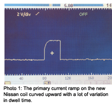
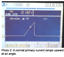
I keep a collection of substitute ignition coils for diagnosing heat-related secondary ignition failures. In this case, temporarily installing a new Nissan coil didn’t solve the problem. With a known-good coil in place, I current-ramped the primary ignition side of the coil. The rise time and dwell time on the primary circuit proved to be extremely erratic. Instead of ramping up on a straight angular line, the ramp curved upward with wide variation in dwell time. See Photos 1 and 2.
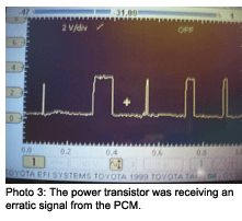
This model of Nissan uses a computer-driven external power diode to trigger the coil. On rare occasions, I’ve had this power transistor cause an intermittent or random stalling complaint. Because the trigger signal from the PCM to the power transistor looked weak on the scope, it appeared that either a defective power transistor might be pulling down the signal from the PCM or that the circuit in the PCM might itself be defective. See Photo 3.
 To test the first diagnostic scenario, I began heating the power transistor to more than 150° with a hand-held hair dryer. The output temperature on a hair dryer is around 150° F, which is close to the ambient air temperature of the engine compartment.
Using a hair dryer to heat the power transistor to equal underhood temperature didn’t cause the engine to stall. Even with the power transistor heated to 150° F, the engine still took its normal hour to stall; obviously, since the power transistor received its trigger signal from the PCM. That left the PCM or the wiring connecting the two as the remaining possibilities.
This scenario presented a chicken-or-egg Diagnostic Dilemma in which economics entered the picture. Should I replace the relatively cheap power transistor before I replaced an expensive PCM? In this case, I gambled on the power transistor and lost. As my hair-dryer test indicated, the power transistor was not at fault. This left me with a PCM failure, which became a cost-prohibitive repair when the resale value of the vehicle and some non-related repair issues were considered.
But logic completed the diagnostic process because, after determining that the failure pattern for the loss of power and stalling complaint was heat and time-related, it became easy to determine that high passenger compartment temperatures were aggravating a circuit fault in the PCM. When I tested during cool, cloudy winter weather, the engine ran fine. But on a sunshine-filled day with high ambient temperatures, the passenger compartment warmed up and caused the PCM to fail.
The High-Idling Tempo
Thinking beyond one’s own experience is often required to diagnose no-code, heat-related intermittent failures. Case in point is a 1994 Ford Tempo equipped with the 2.3L engine and automatic transmission. The car had belonged to an elderly man who had lived on the East Coast. As such, the car had been driven very slowly and possibly without much maintenance.
The next owner, however, began experiencing a fast idle condition that would occur only during the hot summer months in Colorado and most often when climbing a steep, winding mountain road. The Diagnostic Dilemma on this case study was obviously not being able to duplicate the kind of temperatures that seemed to trigger the high-idle problem.
Beginning two years ago, the owner brought the vehicle in with the high idle complaint. Although at that time I had duplicated the 1,600-rpm, high idle complaint, the problem disappeared before I could attach a scan tool and gather any diagnostic data or trouble codes. Due to the inability to duplicate the problem, I was left with educated guess work as to the cause of the failure.
My first educated guess was a throttle position sensor that was failing to return to an exact closed-throttle reading. Although some vehicle operating strategies are more sensitive to closed-throttle voltages than others, I have seen high idle problems caused by variations as small as 1/100 of a volt in the closed-throttle position.
In most strategies, the PCM remembers a specific closed-throttle voltage when the key is turned on. If the throttle position sensor fails to generate the exact closed-throttle voltage each time the throttle is closed, the PCM commands a high idle speed to keep the engine from stalling. In some cases, the high idle range might be as high as 1,600 rpm in this so-called default position.
To keep a long story short, I cleaned the throttle body and replaced the throttle position sensor in my first attempt to solve the problem. A year later, the owner returned with the same complaint. In frustration, I again cleaned the throttle body and replaced the Idle Air Control (IAC), which I decided might be sticking open in high underhood temperatures.
This spring, however, the owner returned with the same high idle complaint. Of course, as soon as he appeared in the driveway, the high idle condition disappeared. Determined to duplicate the condition, the owner drove the Tempo for several hours until he reappeared in my driveway with the engine idling about 1,600 rpm. I quickly grabbed a scan tool and accessed the data stream.
 Although battery voltage, coolant temperature and intake air temperature was normal, I did notice that the PCM was “seeing” a part-throttle condition. I also noticed that the data stream throttle voltage was exactly the same as the voltage measured directly at the throttle sensor.
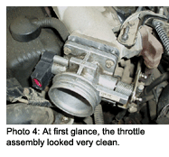
To be quite frank, I had to sleep on this problem for a few days before coming up with a solution. Obviously, high temperatures were keeping the throttle plate and throttle sensor from reaching the closed-throttle position. See Photo 4.
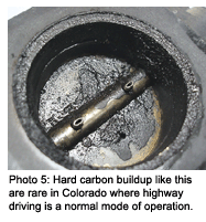
Although I had already cleaned and lubricated the throttle plate and transmission kick-down linkage several times, I removed the throttle body assembly and discovered that the interior of the throttle plate was covered with hard carbon. At this point, let me say that, due to rural driving conditions, I have never witnessed hard carbon buildup on throttle bodies, especially Ford units like this with the Teflon coating on the throttle bore. See Photo 5.
 These Ford throttle bodies require a gentle cleaning process to avoid disturbing the Teflon coating. If the coating becomes rough, the throttle won’t consistently return to the closed position. I have found several penetrating oils that seem to help dissolve carbon deposits without resorting to heavy scrubbing. I eventually removed all of the carbon by carefully brushing it away with a soft toothbrush and towel.
The key to this particular Diagnostic Dilemma was the problem occurring only during high ambient air temperatures. Because the expansion coefficients of the aluminum throttle housing and steel throttle plate are different, I made the assumption that high ambient air temperatures were causing the throttle plate to stick against the hard carbon deposits in the throttle bore. Cooler weather would allow the throttle plate and throttle position sensor to seat in their normal locations.
Summing It Up
Quite obviously, ambient air temperature is the key to both of these cases. In addition, I might mention that the Nissan Quest required a healthy dose of sunshine to boost passenger compartment temperatures, which would aggravate the circuit fault in the PCM to the point it would fail. In the case of the high-idling Ford Tempo, high ambient temperatures also required a boost from high underhood temperatures caused by low-speed, high-load operation encountered in climbing high mountain roads. Both cases required time and patience to determine that high ambient temperatures were indeed the cause of this month’s Diagnostic Dilemmas.


