 This article will explore interpretation of what many have called “the descriptor” for diagnostic trouble codes. This case study is not a difficult one by any means, but important in reference to its understanding. A 1998 Chevrolet Blazer is looked at by the state to determine if the cost to repair this vehicle may exceed what many may deem reasonable. The owner of the vehicle has suffered some financial hardships and we have been asked to take a look at the vehicle.
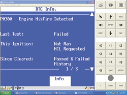
This vehicle is a valuable education in more ways than one as I am teaching an emissions class for the state and it is always great to see how the techs respond to an actual failure event. I have attached a scan tool to the vehicle and am beginning to pull codes, the codes retrieved are as follows: P0300, P1380 and P1351. The screenshots in Figures 1-3 denote the code descriptions.
The first code is evaluated and the Tech 2 misfire graphics screen shows a misfire on cylinder #5 and cylinder #1. A static 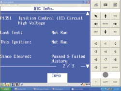 compression test is performed on cylinder #5 with an in-cylinder pressure transducer, which shows that we have compression readings of 60 psi. The team makes a note of low compression for cylinder #5.
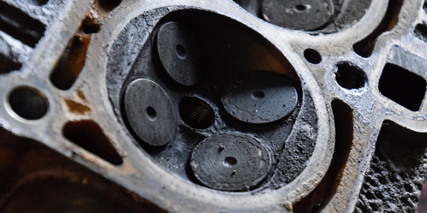
We then proceeded to take a look at cylinder #1. The tech took out the spark plug for cylinder #1 and notes that the spark plug has a hairline crack down the center of the ceramic.
It was interesting to note how many on the evaluation team took on the characteristics of the famous Sherlock Holmes; it was the assurance that no further action was needed and that the process was all too 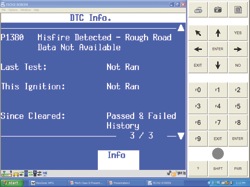 elementary. I have seen this look all too often and respond by taking on the character of Dr. Watson. In order for all of us to have a better understanding of the codes that have set, I always review further the activity that caused the code to set.
I then proceeded to review cylinder #1 under cranking and running conditions with the transducer placed in the spark plug hole. The details of this case were now starting to be revealed; a cranking vacuum test was performed prior to the spark plug being taken out of cylinder #1. The vacuum waveform indicated that we did indeed have a mechanical issue with cylinder #2 as well. Review the waveform in Figure 4. 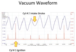
The waveform clearly shows we have a less than acceptable vacuum pull on cylinder #2; I am in search of the truth concerning this observation. I have placed the in-cylinder transducer inside cylinder #1 and will review the running test. I have provided the waveform for your review as well (Figure 5).
I then decided that it was necessary to compare known good, so I obtained a pattern from cylinder #4, the pattern in Figure 6 shows what I saw.
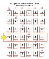
I then challenged the class to give me their analysis of what went wrong on cylinder #1. 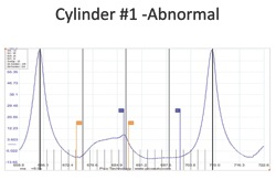 I have documented all data and have drawn a conclusion on this. I suspect the problem lies on the exhaust side, but I will challenge all of you to determine what happened in terms of the valvetrain. Please e-mail me your thoughts and let’s have a very good discussion on this. I have provided a piston position chart (Figure 7) to assist in the analysis of what may have happened in reference to this mechanical failure.
The final analysis on this case study is the “misfire detected-rough road data not provided.” The students felt this may have been a crank angle relearn or an HVS distributor issue.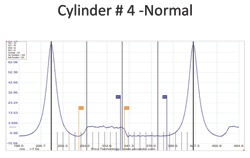 It was neither the case, the code set due to an ABS light being illuminated. Please e-mail me your thoughts at [email protected]. We will provide final thoughts on this in our next issue. This case will remain open until then.