This article will continue the work we started in the June 2011 Pulling Codes article. Part I outlined how we used relative compression to find a fault mechanically. In this article, we will focus on exhaust waveforms (tailpipe analysis) to gather data. In order to have an understanding of this concept, one must envision the four-stroke cycle at the time the plug fires as a reference. This denotes the end of our compression stroke, but the beginning of the power stroke for that cylinder. (Keep in mind that this is just a visual reference, other factors are added in.) The piston then travels 180° and, in theory, we are now at the beginning of the exhaust stroke for that cylinder.
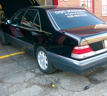
For this Pulling Codes’ subject vehicle, I have placed in the tailpipe a tool for evaluating exhaust pulses, the tool is called a “first-look sensor,” which will allow me to look at the exhaust pulses on a labscope for analysis.
Our reasoning for promoting this analysis is to be able to evaluate engine families where it may be very difficult to use conventional methods to make a decision on which is the misfiring cylinder. There will be consistent exhaust pulses that will be witnessed at the tailpipe based on normal operation. If you’re interested in learning more about this tool, you can go to www.senxtech.com and download a training program from the website. I’ve found this tool to be one of great value for me when it’s time to confirm what we believe to be true.
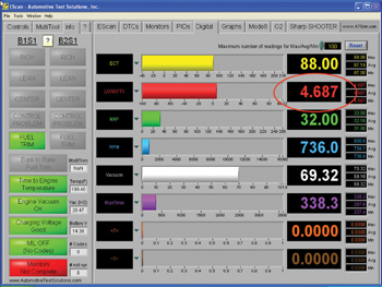
Our subject vehicle for this Pulling Codes case is a 1996 Mercedes-Benz, I received a call from a very good friend of mine who stated that the engine appeared to be misfiring on cylinder #6. A quick review of scan data showed burn time of 1.0 ms for all cylinder pairs except 2 and 5; for those it showed a burn time of 2.5 ms. This is interesting to note, as my friend stated that the suspected cylinder is cylinder #6.
It has also become very important to take a look at fuel trims when misfire activity is taking place. It has been researched and noted that ignition misfires don’t have a significant impact on fuel trims. However, our research showed that fuel-related issues do have a significant impact on fuel trims. The scan tool shows fuel trim values that are less than +5%, which highly implies the misfire activity may be ignition related. See Figure 1.
The next four labscope patterns show the activity we witnessed while the engine was running at idle. I will give a play-by-play analysis of our interpretation. Let’s start with Figure 2. 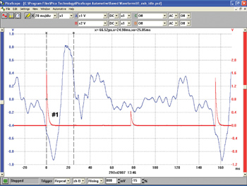 We’ve placed the first-look sensor in the tailpipe and have obtained the following pattern. It’s difficult to evaluate this pattern without placing a template over it, so in Figure 3, we’ve got the same pattern with a template, and have identified our ignition synch for cylinder #1.
 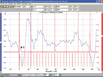 The ignition synch is when the spark plug for cylinder #1 actually fired.
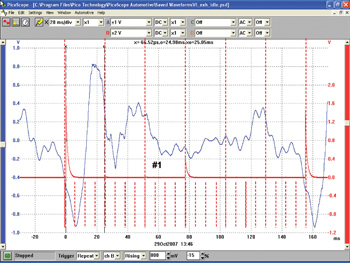
In Figure 4, note that the #1 has moved 240° and appears more to the right of the pattern in reference to what we saw in Figure 3; this is the exhaust stoke area for cylinder #1.
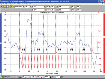
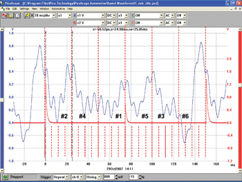
In Figure 5, we are now able to identify all cylinders and their relationships in reference to their exhaust pulses. 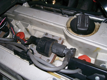 It’s quite evident that cylinder #2 has strange pattern behavior; this is what denotes the misfire activity for cylinder #2. I checked the scan tools for codes and all codes were erased by the time I arrived at the shop. There was no record of a code P0306. In fact, there were no codes stored at all, but my friend insisted that he did indeed witness the P0306.
So I started looking for some insight into his claim; I swapped my suspect coil with cylinder #6 and then checked to see if the misfire followed the suspect coil. After coil #2 was placed in cylinder #6, the cylinder started to misfire; it was clear that the guilty party was this coil.
The following three scope patterns prove and support this claim. Figure 6 on page 15 shows that the strange activity now occurs for a different cylinder. In Figure 7, it becomes very clear that the misfiring cylinder is different from what we previously saw earlier.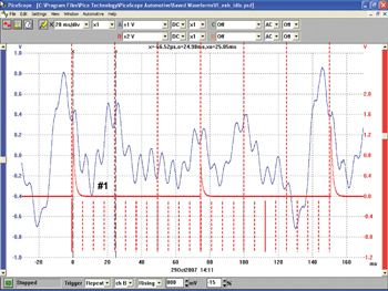 In the Figure 8, it’s now clear that cylinder #6 is now the misfiring cylinder. The bad coil assembly was replaced and the misfire was gone.
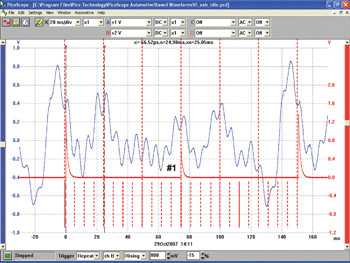
 Our final pattern, Figure 9, shows what normal activity looks like. It’s our hope to investigate misfire activity from four vantage points: cranking current, vacuum, exhaust and in-cylinder analysis.
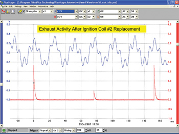
This Pulling Codes case is now closed. There are two more parts to this story to be explored.
And Part I can be found by clicking here.
I would like to thank all of you for your comments and involvement with the Pulling Codes articles. — Carlton Banks