By Chris Burton, ALLDATA editor, and Jeff Webster,
ALLDATA technical writer
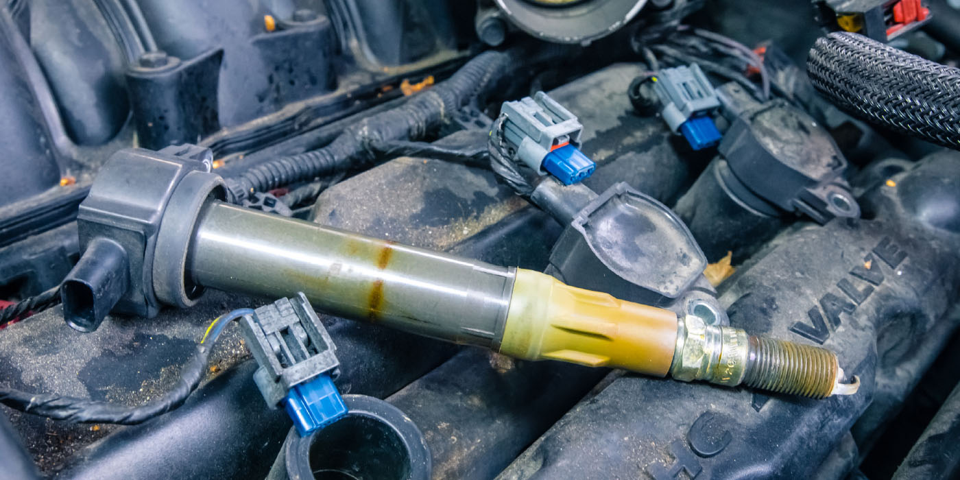
Some Buick Lucerne owners may comment on a vibration and/or growl type of noise during light throttle drive-aways at approximately 1,800 rpm. 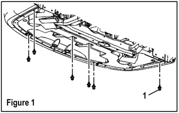
This condition may be caused by the front edge of the front engine mount bumper stop grounding out to the inside vertical surface of the restrictor plate.
The bumper stop lacks sufficient travel and/or the rubber material to isolate the ground-out.
Applicable Models: 2006 Buick Lucerne with 3.8L V6 Engine (VIN 2 – RPO L26)
Repair Procedure
1. Raise and suitably support the vehicle.
2. Remove the front air deflector fasteners (QTY: 17) (1, Figure 1).
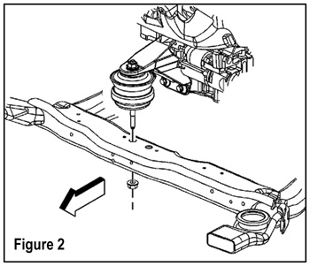 3. Remove the engine front mount to frame nut (Figure 2).
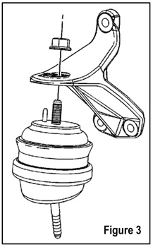
4. Remove the engine mount bracket nut (Figure 3).
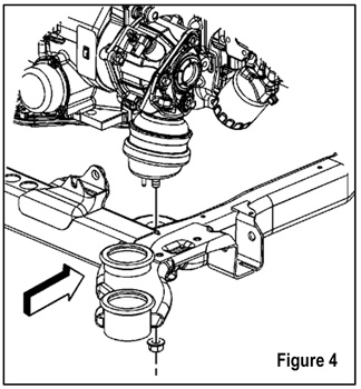
5. Remove the engine right rear mount to frame nut (Figure 4).
6. Place a suitable hoist/adjustable jackstand and a block of wood under the oil pan.
7. Lift the engine until the engine front mount lower stud clears the frame.
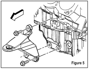
8. Remove the engine mount bracket bolts (QTY: 3) (Figure 5).
9. Remove the bracket and front engine mount.
10. Replace the front engine mount with P/N 15910501.
Note: Use the correct fastener in the correct location. Replacement fasteners must be the correct part number for that application.
 Fasteners requiring replacement or fasteners requiring the use of thread locking compound or sealant are identified in the service procedure.
Do not use paints, lubricants or corrosion inhibitors on fasteners or fastener joint surfaces unless specified.
These coatings affect fastener torque and joint clamping force and may damage the fastener.
Use the correct tightening sequence and specifications when installing fasteners in order to avoid damage to parts and systems.
11. Install the new engine mount, bracket and bolts (Figure 5). Tighten the bracket bolts to the engine to 52 lb.-ft (70 Nm).
12. Install the engine mount bracket nut and hand-tighten (Figure 3).
13. Lower and align the engine front mount stud back onto the frame and hand-tighten (Figure 2).
14. Install the engine right rear mount to frame nut and hand-tighten (Figure 4).
15. Remove the hoist/adjustable jackstand and block of wood from under the oil pan.
16. Tighten the engine mount fasteners to the following specifications and in this sequence:
 a. Tighten the right rear engine mount nut to 59 lb.-ft. (80 Nm).
b. Tighten the left rear engine mount nut to 59 lb.-ft. (80 Nm).
c. Tighten the transaxle mount to frame nut (QTY: 2) to 37 lb.-ft. (50 Nm).
d. Tighten the front engine mount lower nut to 59 lb.-ft. (80 Nm).
e. Tighten the front engine mount upper nut to 59 lb ft (80 Nm).
f. Lower the vehicle.
g. Tighten the front engine mount bracket nut to 59 lb.-ft. (80 Nm).
h. Install the front air deflector and fasteners (QTY: 17) (Figure 1).
17. Test-drive the vehicle to confirm the repair.
By Chris Burton, ALLDATA editor, and Jeff Webster,
ALLDATA technical writer
 Courtesy of ALLDATA.