th of the disc brake pads, replace the disc brake pads.
Rotors
The rotor specs for both brake packages are tight, but the vehicle is not known for being runout sensitive. The rotor plates have enough material to get up to two brake jobs out of the rotors. GM recommends the use of an on-the-car lathe and the use of Brake Align shims to correct assembled lateral runout.
ROTOR SPECS
Front Brake Rotors (J55)
Diameter: 330.0 mm (12.99 in)
Discard: 36.0 mm (1.417 in)
Maximum Allowable Assembled Lateral Runout: 0.05 mm (0.002 in)
Maximum Allowable Thickness Variation : 0.025 mm (0.001 in)
Minimum Allowable Thickness after Refinishing: 37.0 mm (1.457 in)
New Rotor Thickness: 38.00 mm (1.496 in)
Rear Brake Rotors (J55)
Diameter: 325.00 mm (12.79 in)
Discard Thickness: 27.5 mm (1.083 in)
Max Allowable Assembled Lateral Runout: 0.05 mm (0.002 in)
Maximum Allowable Thickness Variation: 0.025 mm (0.001 in)
Minimum Thickness after Refinishing: 28.0 mm (1.102 in)
Thickness (New, J55): 29.0 mm (1.142 in)
Front Brake Rotors (JL9)
Diameter: 323.0 mm (12.72 in)
Min Thickness: 28.6 mm (1.126 in)
Max Allowable Assembled Lateral Runout: 0.06 mm (0.002 in)
Max Allowable Thickness Variation: 0.025 mm (0.001 in)
Rotor Thickness: 30.0 mm (1.181 in)
Rear Brake Rotors (JL9)
Diameter: 292.00 mm (11.50 in)
Min Thickness: 10.5 mm (0.413 in)
Max Allowable Assembled Lateral Runout: 0.06 mm (0.002 in)
Max Allowable Thickness Variation: 0.025 mm (0.001 in)
Rotor Thickness: 12.00 mm (0.472 in)
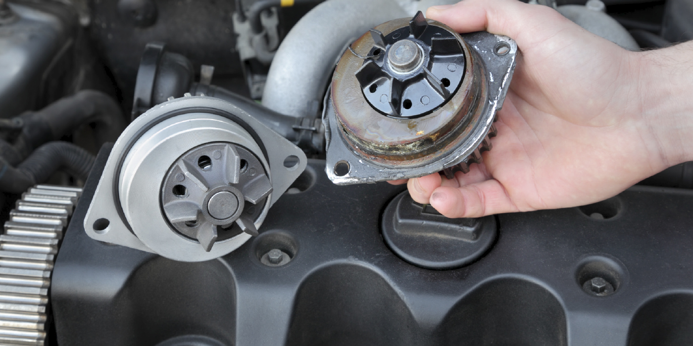
Calipers
The calipers used on the Lucerne are common with several GM platforms. The J55 package uses phenolic pistons in the front calipers. The JL9 package uses metal pistons. It is recommended that new abutment clips are used every time the pads are replaced.
The rear calipers are a single piston floating design. They are actuated by cables to operate the emergency brakes. To remove the rear pads, disconnect the cables at the caliper and use the right tool to turn the piston.
It is recommended that if pad taper is greater than 0.15 mm (0.006 in), that caliper piston and hardware is inspected and replaced if necessary. GM recommends applying a thin coat of high temperature silicone lube to the front brake caliper pin bolts.
Bleeding
The DTS can be bled using conventional procedures without a scan tool. But if a hydraulic component is replaced, bleeding with a scan tool is recommended. The Auto Bleed Procedure may be terminated at any time during the process by selecting the exit menu.
Procedure
1. Remove all four tire and wheel assemblies.
2. Inspect the brake system for leaks and visual damage. Repair or replace components as needed.
3. Install a scan tool.
4. Turn the ignition ON, with the engine OFF.
5. With the scan tool, establish communications with the ABS system. Select Special Functions. Select Automated Bleed from the Special Functions menu. The Automated Bleed function will take five to 20 seconds.
6. Follow any screen instructions.
7. Remove the scan tool.
8. Following the directions given on the scan tool, pressure bleed the base brake system.
9. Follow the scan tool directions until the desired brake pedal height is achieved.
10. If the bleed procedure is aborted, a malfunction exists. Perform the following steps before resuming the bleed procedure:
• If a DTC is detected, refer to DTC list.
• If the brake pedal feels spongy, perform the conventional brake bleed procedure again.
11. When the desired pedal height is achieved, press the brake pedal to inspect for firmness.
12. Remove the scan tool.
13. Install the tire and wheel assemblies.
14. Inspect the brake fluid level.
15. Road test the vehicle while inspecting that the pedal remains high and firm.
Warning: GM recommends that you use the following procedure to seat the pads against the rotor before you burnish the pads and rotors.
1. With the engine OFF, gradually apply the brake pedal to approximately 2/3 of its travel distance.
2. Slowly release the brake pedal.
3. Wait 15 seconds, then repeat steps 1-3 until a firm brake pedal apply is obtained; this will properly seat the brake caliper pistons and brake pads.
4. Fill the brake master cylinder reservoir to the proper level.
5. Burnish the pads and rotors.