This information is from Comp Performance Group and is intended to cover the shaft-mounted rocker systems for Small Block and GEN III Chevrolet engines only. For information specific to other shaft rocker systems you should refer to the manufacturer’s instructions.
 1) The rocker arm roller tips must be immersed in oil for a minimum of 3 hours to allow full lubricant penetration of the roller tip and axle. A household ice tray works well for this purpose. Please note that it is absolutely critical that all shaft rocker components be thoroughly pre-oiled prior to use.
2) Thoroughly inspect both cylinder heads to ensure that they are free of any obstructions that may prevent the rocker stands from bolting down evenly.
3) After removing the old rocker arm studs from the cylinder heads, inspect all rocker stud bolt holes to ensure that the threads have not been damaged during removal of the studs. Running a thread chaser through all of the holes will guarantee clean threads and a secure mounting point for your new COMP shaft rocker system.
4) Prior to torquing any of the rocker stand bolts, verify that all rocker stand bolts can be threaded completely through the rocker shafts and into the rocker arm stud holes. Any bolt that does not thread all the way into the stud hole should be shortened using a bench grinder. Be sure to clean up the threaded bolt ends with a thread chaser after grinding.
5) Torque the 7/16˝ stand bolts to 45 ft.lbs. Bolts that thread into an intake runner should be coated with a good thread sealant.
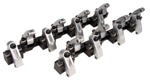
6) Install the rocker arms onto the rocker arm shaft with a shim on either side of the rocker, and place a lock ring on the outside of each shim. The shims prevent side pressure from damaging the shaft bearings. Install the 5/16” Torx head bolts through the rocker shafts into the rocker stands, and torque them to 25 ft.lbs.
7) Place a few drops of oil on the valve lash adjuster threads prior to installation in each rocker arm. Tighten the adjuster by hand until bottomed out. Back the adjuster out 1 turn, and thread the adjuster nut onto the adjuster. Tighten the adjuster nut to 45 ft.lbs. to seat the adjuster. Note that it is absolutely critical that the adjuster is backed out one full turn prior to torquing the adjuster nut. Failure to do so will result in damage to the adjuster and rocker arm.
8) Once the valve lash adjuster has been seated, loosen the adjuster nut and set the adjuster for valve lash. Retighten the adjuster nut to 35 ft.lbs. Do not run the rocker arm with the adjuster bottomed out, as doing so will result in damage to the rocker arm and other engine components.
9) Place the tip of an oil can against the oiling hole in the adjuster, and pump the handle until oil comes out of the oil passage behind the rocker arm roller tip.
Post Installation Maintenance
• The synchronized oil system must be inspected periodically for obstructions that may prevent proper rocker arm oiling.
• After the valve has been adjusted to camshaft specifications, verify that the 12 pt adjuster nut has been torqued to 35 ft.lbs. Failure to do may result in severe engine damage if the adjuster nut should come loose while the engine is running.
Note: Do not re-tap the 7/16” adjuster hole with any type of tap other than a 7/16˝-20 roll forming tap (Union-Butterfield p/n 1310209 or similar) as doing so will damage the rocker arm beyond repair.
Tech Tip courtesy of Comp Cams (www.compcams.com).