on, with a number of incident memory entries with regard to the throttle valve are stored in the ECM. In most cases, the entries are sporadic.
The most frequent incident memory entries are:
– P1545 (throttle control malfunction).
‒ P0121 (throttle potentiometer – G69 implausible signal).
‒ P0123 (throttle potentiometer – G69 signal too big).
‒ P0221 (angle transmitter 2 for throttle actuator G188 implausible signal).
‒ P0222 (angle transmitter 2 for throttle actuator G188 signal too small).
Cause:
There is contact resistance in the ECM wiring – throttle valve.
Service Notes:
• For repairs on vehicle electrical systems, soldering is not permitted.
• Do not repair crimp connectors. If necessary, lay a wire parallel to the inoperative wire.
• After crimping, crimp connections must be heat-shrunk using a hot air gun to prevent moisture penetration.
• Yellow wires are to be used exclusively for wiring harness repairs.
• Mark repaired areas using yellow adhesive tape.
• Yellow wires and areas in the wiring harness wrapped with yellow adhesive tape mark a previously performed repair.
• Perform a function test after each repair. If necessary, check DTC memory, erase and/or bring systems into basic setting.
Procedure:
1. With the ignition switched off, disconnect the battery ground (GND) cable. Disconnecting the battery ground wire is necessary to work safely on the vehicle’s electrical system.
Warning: The above step must be completed to ensure safety during the repair. Also, observe all country-specific regulations.
2. Use the applicable repair manual in Elsa in addition to the following description. Check ETKA to determine if you need set 1 or set 2.
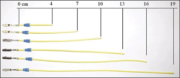
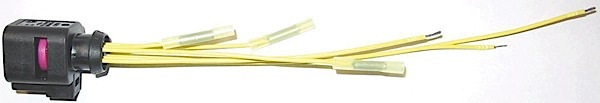
3. Lengthen wires and preassemble seals according to Figure 1.
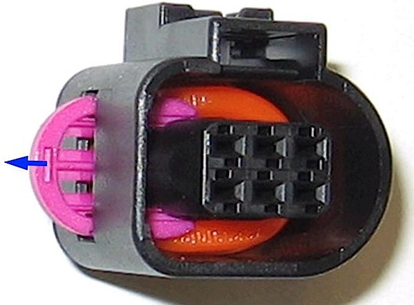
4. On the new housing, remove the pink lock with a small flathead screwdriver. Use the slot marked in Figure 2.
5. Insert all terminals into the housing until they audibly click.
6. Reinstall the pink lock.
7. Using the appropriate assembly tool, slide the single wire seal up the repair wire until it contacts the housing. Continue to slide the single wire seal into the housing as far as the stop (Figure 3).
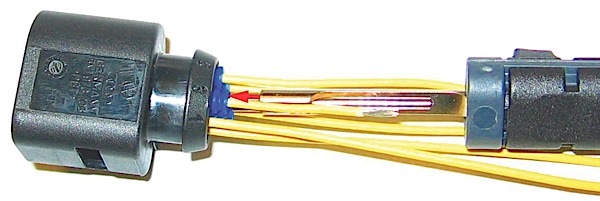
8. Strip the wires 6-7 mm using tool VAS 1978/3. Install crimp connectors using crimping pliers (base tool) VAS 1978/1-2 with the head VAS 1978/1-1 (Figure 4).
9. Remove the car harness insulation to the appropriate length (approximately 24 cm).
10. Lay the new harness beside the old harness. Cut the original wires to fit the new harness.
11. Twist wires 3 and 5 and 1, 2, 4 and 6 as they were originally.
12. Crimp the connections.
13. Use shrink tip (VAS 1978/15) with a hot air gun 220 V/50 Hz (VAS 1978/14) to complete the installation of the shrink tubes.
Note: When heat-shrinking crimp connections, be careful not to damage any other wiring, plastic parts or insulating material with the hot nozzle of the hot air gun. Always observe operating instructions of heat gun.
14. Re-insulate the harness with yellow tape.
15. Check for proper function. If necessary, check DTC memory, erase and/or bring systems into basic setting.
Note: If faults reoccur after repair, replace the main throttle.