This article documents a No Code Analysis for a Variable Cam Timing (VCT) Issue; this is a story that involves multiple misfire issues due to cam timing.
Our diagnostic journey this month begins with a 2005 Ford F-150 Super Duty. Note: Before starting your diagnosis, you should first check the oil level and quality for the VCT system. There are also very good websites that provide known-good waveform libraries. Contact me at [email protected] and I will provide additional information on those sites.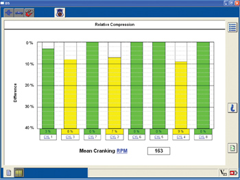
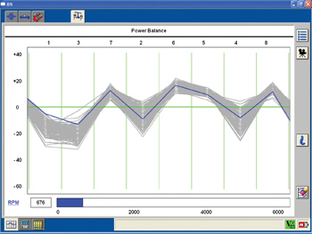
Our subject vehicle has a 5.4L engine with three valves per cylinder. The engine starts and runs; the idle quality is very poor; and cylinders 2, 3 and 4 have misfire activity. The Ford IDS scan tool is used to begin a mechanical analysis of the system. The activity in Figure 1 was noted.
The power balance option on the IDS shows we have misfire activity on cylinders 3, 2 and 4; see Figure 2. The test shows that cylinder 1 would also misfire at times. An additional test is performed using the relative compression test option and it also confirms the same as the previous test.
The fuel trims were reviewed and it showed the total fuel trim correction on bank 1 to be -4.76%, the total fuel trim correction on bank 2 is 25.21%. We would like to see less than +/-10% on both banks.
Data Graphing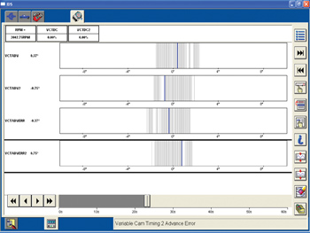
The first dynamic to perform on this engine family is an idle speed test. We would like the cam angles (no phasing) to be in a range of +/-2 degrees at idle. The idle test shows that the cam phasing data is within the proper range. Figure 3 shows the following values: VCTadv1 = 0.37 degrees, VCTadv2 = 0-.75 degrees, VCTadverr1 = -0.37 degrees and VCTadverr2 = 0.75 degrees (idle speed values appear to be normal). 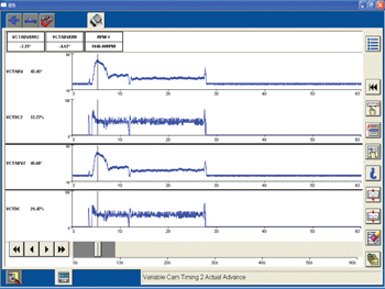
The second dynamic test is the brake torque test with the transmission gear in reverse (automatic transmission). The line pressures for the transmission will be higher by performing the test in this manner. The ultimate goal of this test is to be able to see the actual cam phasing occur under a load condition. 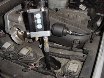 When the brake torque test was performed, the VCTadv PID shows that the cams are being retarded equally under a brake torque. See Figure 4. It appears that there is not an issue with the variable cam timing system. The PIDs do not support our thoughts, but there does appear to be a cam timing issue. The third dynamic test performed was an in-cylinder analysis, a transducer will be used to perform this test with a lab scope. Photo 1 shows the setup.
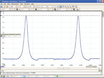
Figures 5a, 5b, 6a and 6b make a comparison between cylinders 1 and 5 on this engine family. It appears that based on the data, cylinder 5 is a known-good because there was no misfire activity noted on this cylinder.
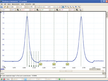
A review of the waveforms shows that cylinder 1 has a lower cranking compression (166 psi) compared to cylinder 5 (214 psi). 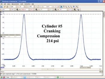
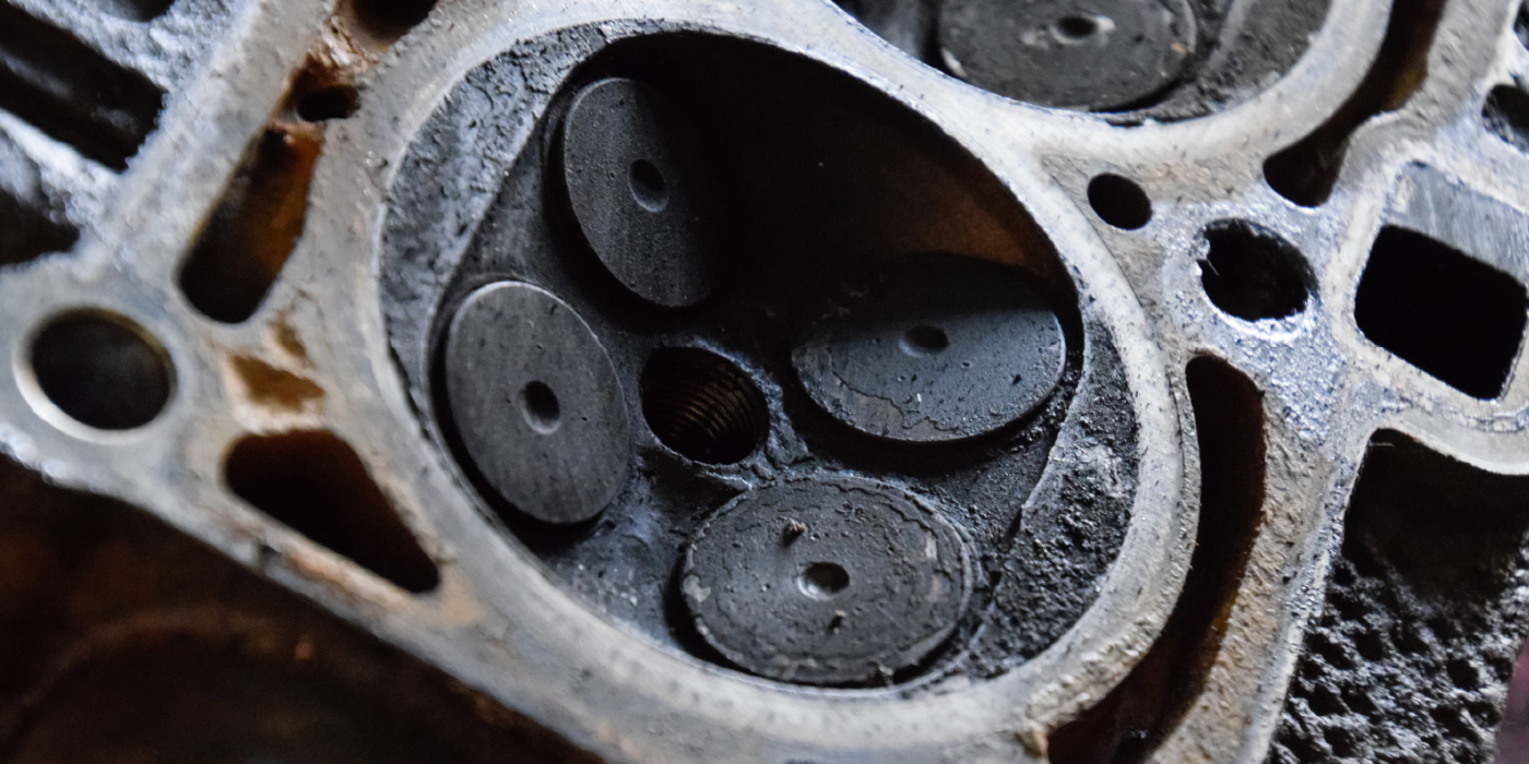
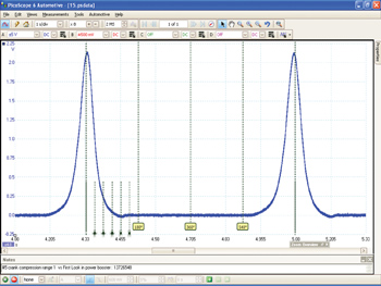 The cranking compression EVO (Exhaust Valve Opening) is about 30 degrees BBDC (before bottom dead center) and cylinder 5 cranking compression EVO is about 60 degrees BBDC. Bank 1 cam appears to be about 30 crank degrees retarded compared to bank 2. A breakdown of the engine revealed the following per the cam sprocket: the pin on the sprocket sheared and caused the problem we witnessed on this vehicle. Photo 2 shows a good cam sprocket.
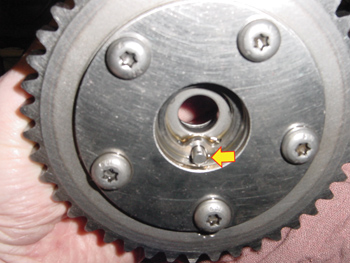
This Pulling Codes case is now closed.