This bulletin provides information related to the Oil Control Valve (OCV) used in Constant Variable Valve Timing (CVVT) systems. If, at any time, the OCV is suspected as a cause of rough idling, poor acceleration, camshaft timing misalignment-related trouble codes, misfire-related trouble codes, etc., on a Kia vehicle equipped with a CVVT system, be sure to perform the OCV inspection procedure below before replacement.
If the OCV operates normally, inspect for other engine malfunctions. Do not replace the OCV.
Note: Make sure the oil filter is OE; aftermarket oil filter flow rates differ and may affect the CVVT system’s performance. See Fig. 1. 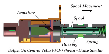
Related Diagnostic Trouble Codes:
P0011 – “A” camshaft position – Timing over-advanced or System performance (Bank 1)
P0012 – “A” camshaft position – Timing over-retarded (Bank 1)
P0014 – “B” camshaft position – Timing over-advanced or System performance (Bank 1)
P0015 – “B” camshaft position – Timing over-retarded (Bank 1)
P0016 – Crankshaft position-Camshaft position correlation (Bank 1 Sensor A)
P0018 – Crankshaft position-Camshaft position correlation (Bank 2 Sensor A)
P0021 – “A” camshaft position – Timing over-advanced or System performance (Bank 2)
P0022 – “A” camshaft position – Timing over-retarded (Bank 2)
P0300 – Random/Multiple cylinder misfire detected
Basic Inspections:
– Monitor the waveforms of the crankshaft and camshaft position sensors with GDS.
– Check if the OCV connectors are securely connected and the pin tension is correct.
– Check that OCV connector seals are well seated; LH and RH OCVs are installed in place.
Note: The LH and RH OCV connectors are different in colors on V6 configurations.
– Measure resistance between the OCV power and ground terminals.
> If resistance is within specifications, proceed to the OCV Test: Determine if OCV operates normally by providing 12V power and ground.
– OCV is operating as designed; inspect other related areas.
> If resistance is not within specifications, replace the affected OCV. (See chart below.)
OCV Supplier OCV Coil resistance (at 68° F)
Denso 6.9 ~ 7.9 Ω
Delphi 6.7 ~ 7.7 Ω
Siemens 6.8 ~ 8.0 Ω
– If the OCV does not move or cycle, examine for foreign objects like flashing or aluminum chips inside the OCV.
> If no foreign objects are found, replace the OCV.
> If foreign objects are found in the OCV, remove the foreign material and then verify that the DTC or driveability concern is corrected.
1. Measure the resistance between the OCV power and ground terminals.
Measured Resistance (68° F) Action to Take
Denso (6.9 ~ 7.9Ω) Check if the OCV
Delphi (6.7 ~ 7.7Ω) operates normally by
Siemens (6.8 ~ 8.0 Ω) providing 12V power.
(See Step 2.)
Infinity Open circuit →
Replace the OCV.
Abnormally low or Short circuit →
zero resistance Replace the OCV.
2. Check if the OCV operates normally by providing a 12V power supply. Do not apply voltage for longer than five seconds at a time; do not overheat the OCV windings. 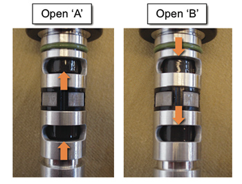
Note: Careful attention is necessary to avoid a short circuit when providing the OCV with 12V power because the spacing between the OCV power and ground terminals is very narrow.
3. When 12V power is provided to the OCV, the OCV must move forward as shown in Fig 2.
A: Maximum retarded valve timing condition (12V not provided), Normally open. 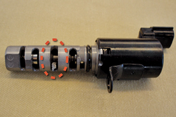
B: Maximum advanced valve timing condition (12V provided), Closed when energized.
4. If the OCV does not move forward, examine it carefully for a foreign object like an aluminum chip or flashing, which maybe jammed inside the OCV passage. See Fig. 3.
– Blow out the foreign object using compressed air, reuse the OCV and then verify that the fault is corrected.
The OCV can be replaced for the following conditions:
• Resistance is out of specification
• Valve does not move when voltage is applied
• Foreign debris cannot be removed from the OCV.
Courtesy of Kia Motors America.


