Vehicles:
• Ford: 1997-2002 Expedition; 1997-2003 F-150; 2001-2004 Escape.
• Lincoln: 1998-2002 Navigator; 2002-2203 Blackwood
Service Information:
Note: For Escape vehicles, this tie rod end inspection procedure should only be complete on the outer tie rods. For Escape inner tie rod inspection procedures, refer to workshop manual section 211-00.
Step 1 — Free Play
Check the outer tie rod ends by grasping by hand and push up and down. Check the inner tie rod ends, pushing them front to rear. If any free play is observed in a joint, it is worn and should be replaced.
Step 2 — Stud Lash — Free Play
While vehicle is on the ground or on a drive-on hoist, have an assistant rotate the steering wheel rapidly back and forth from 10 o’clock to 10 o’clock while observing the inner and outer tie rods. If the outer tie rod ends have any vertical movement or the inner tie rod ends have any horizontal movement, the tie rod end with the observed movement should be replaced.
Step 3 — Seal Inspection
Raise the vehicle on a hoist and remove the front wheels. The wheels will need to be turned to the right in order to inspect the passenger side inner tie rod end and to the left to inspect the driver’s side inner tie rod end. Inspect all four seals for tears, perforations and wear. If there is any indication of wear or perforations on the seal, that tie rod end should be replaced.
Step 4 — Stud Corrosion
For Escape vehicles: If squeak is noticed during Step 2, disconnect the tie rod from knuckle and articulate stud in socket. If squeak is verified, replace part. While pushing down on seal, at stud end, if corrosion is present at contact point at base of stud, replace part.
For all other vehicles covered in this article: Using a wrench, rotate the tie rod end so that the front of the seal on the outer tie rod end is expanded (Figure 1). 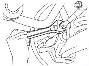
Using a putty knife or other hard, flat, dull object, lift the bottom of the seal up, exposing the stud (Figure 2). 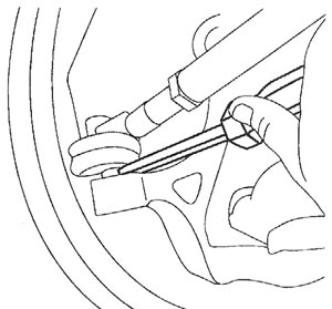
If any water escapes from the seal in the form of bubbles or in a liquid form, that tie rod end should be replaced. Closely examine the stud for signs of corrosion, especially around the interface with the knuckle. A rag might be needed to clean off any grease on the stud that impairs a good visual inspection. If there is any sign of corrosion, that tie rod end should be replaced.
Note: If any tie rod ends are removed, inspect the seal and the stud again noting any differences in visual perceptions from when the part was on the vehicle. Checking the stud after removal helps improve consciousness of issues when inspecting parts on vehicle.
Technical service bulletin courtesy of Mitchell 1.
For more information on Mitchell 1 products and services, automotive professionals can log onto the company’s website at www.mitchell1.com.