Understanding how relays work can help counter pros select an appropriate replacement – even without a catalog.
Relays tend to cause some confusion for many customers, as well as for many counter pros. The wide variety of relay configurations, applications and uses can make selection difficult, especially when catalog information is unavailable or incomplete. Understanding how relays work and “reading” the relay’s printed schematic can help ensure that you get the appropriate relay – even without the aid of catalog listings or interchanges.
Relays are used throughout the vehicle’s electrical systems, allowing low-current switches to control higher-current components. Think of all the small-gauge wiring circuits found throughout a modern vehicle, and then consider the high-current loads that these circuits control. Electric motors, solenoids and incandescent lighting all draw considerable power, but many of their control circuits rely on relays to isolate and switch the high and low current flows.
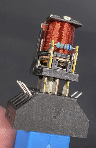
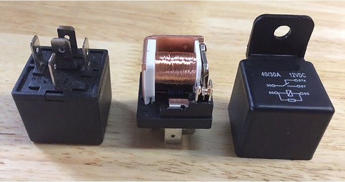
A relay is an electromechanical switch that uses a magnetic field to “pull” a set of contacts together, making or breaking a circuit. It is divided into two halves: a “control” circuit with a magnetic coil and a “load” circuit that contains the contacts that make up the switching mechanism. On the control side, when current flows through the coil, a magnetic field is created, pulling the armature away from one contact to the other, completing a circuit on the “load” side of the relay.
The wide variety of relay configurations, applications and uses can make selection difficult.
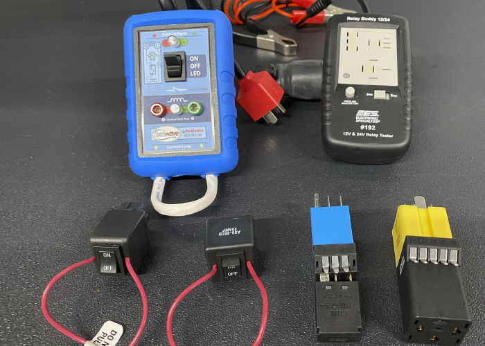
Depending on the type of relay, the number of pins and its internal construction, it may open or close a circuit feeding one or more components. The most common types of relays are known as ISO relays, and come in two sizes. The ISO mini relay is an approximately 1-inch cube, with either four or five numbered pins arranged in a standardized “cross” pattern. The ISO micro relay is approximately half the size of the ISO mini relay, with its pins arranged in a sort of “T” pattern. Both work in the same manner.
Internal Connections
The diagram printed on the side of the relay will show you the internal connections between each numbered pin of the relay. Pins 85 and 86 make up the “control” circuit, with the coil in between. Pins 30, 87 and 87a comprise the “load” circuit, which contains the switch. The broken line between the two circuits represents the “action” of the magnetic coil. A relay schematic will always show the circuit “at rest” or de-energized. At rest, pin 87 is normally open (NO), and if present, pin 87a is normally closed (NC). Pin 30 is known as the “common” terminal, usually a fused 12-volt supply.
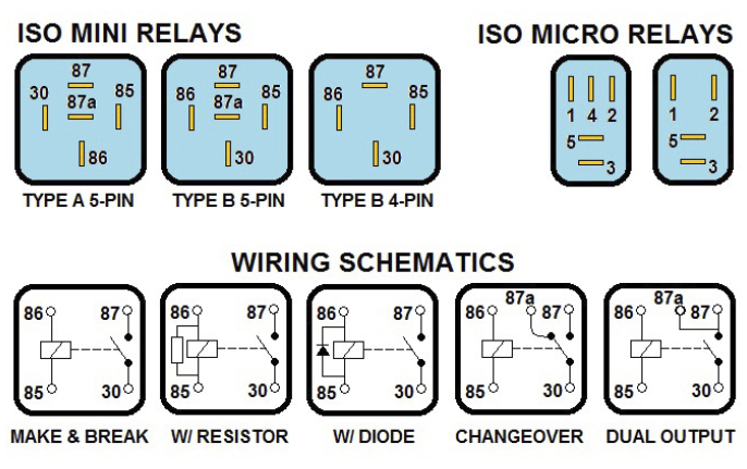
Also included in the diagram are the voltage and amperage rating and (if we’re lucky) a usable part number to reference. Some relays also include a resistor or diode, which helps prevent back-feeding of voltage and damage to sensitive electronics. Although it’s recommended that the 12-volt supply be connected to pin 85, pins 85 and 86 can be wired without worrying about polarity, unless a diode is present. In diode-equipped relays, the 12-volt supply must be connected to pin 86 to prevent diode damage.
Numbering System
ISO micro relay pins are numbered 1 through 5. Their functions are as follows:
- No. 1 and No. 2: control/coil circuit (same as 85 and 86)
- No. 3: common (same as 30)
- No. 4: normally closed (NC), same as 87a
- No. 5: normally open (NO), same as 87
When a direct catalog lookup or OEM interchange is unavailable, comparing the pin layout and the schematic can help you find a suitable replacement from your shelf stock. When substituting relays, be extremely careful to match pin numbering and location between the original and replacement relays. ISO mini relays may be of the type “A” or type “B” design, with the 30- and 86-pin locations reversed. Using the wrong relay can cause circuit and relay damage! If the customer’s original ISO relay is a four-pin design (also known as a “make-and-break” relay), a five-pin “changeover” relay may be substituted, providing that the fifth pin is not connected to anything. In many fuse boxes, when a four-pin relay is used, there still is an empty cavity in the “87a” position. If the cavity has a terminal installed, DO NOT attempt to install a five-pin relay!