Hyundai Tech Tip: Engine Vibration Due To Misaligned Timing Marks On The Oil Pump

Hyundai Tech Tip: Engine Vibration Due To Misaligned Timing Marks On The Oil Pump

This bulletin provides information regarding the proper indexing of the timing marks of the Oil Pump Module during in-vehicle installation on vehicles equipped with Theta four-cylinder engines. If the Oil Pump Module timing marks are improperly indexed, abnormal engine vibration may result. Follow the service information outlined in this bulletin whenever a new or existing Oil Pump/Balance Shaft Module (BSM) is being installed.

Models:
2006-2015 Sonata equipped with 2.0T or 2.4L engines
2010-2014 Santa Fe equipped with 2.0T or 2.4L engine
2010-2014 Tucson equipped with 2.4L engine

This bulletin provides information regarding the proper indexing of the timing marks of the Oil Pump Module during in-vehicle installation on vehicles equipped with Theta four-cylinder engines. If the Oil Pump Module timing marks are improperly indexed, abnormal engine vibration may result. Follow the service information outlined in this bulletin whenever a new or existing Oil Pump/Balance Shaft Module (BSM) is being installed.

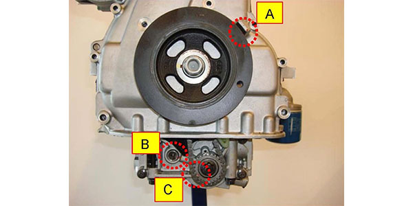
1. Prior to installing the lower oil pan, confirm the proper indexing of the Oil Pump Module timing marks. Locate the timing marks for: (A) crankshaft pulley and timing chain cover; (B) counterbalance driven shaft and housing; and (C) oil pump driven sprocket and housing.


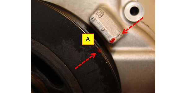
2. Rotate the (A) crankshaft pulley until the notched mark on the pulley lines up with the 0° TDC sight mark “T” on the timing chain cover.

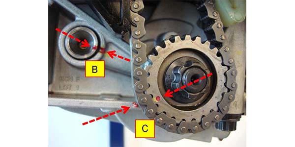
3. Confirm that the (B) counterbalance driven shaft and housing marks are lined up when the (C) oil pump driven sprocket and housing marks are lined up. If the (C) oil pump driven sprocket and housing marks are not lined up, then repeat Step 2 above by rotating the crankshaft pulley one complete turn clockwise. Step 2 may need to be repeated up to three times until the marks for both (B) and (C) line up.
• The counterbalance driven shaft (B) turns twice the crankshaft speed.
• The oil pump driven sprocket (C) returns to the same indexed position after four complete clockwise rotations of the crankshaft pulley (A).
• Reinstall the oil pump chain to the driven sprocket if all marks are not aligning correctly.

Courtesy of Mitchell 1.

You May Also Like

Lifter Deactivation

The area of contact between the lifters and cam lobes is the highest loaded surface inside an engine.

The basic function of a valve lifter is pretty simple. It sits on the camshaft and transfers the motions of the cam lobe up through the pushrods and rockers to open and close the valves. The size and shape of the cam lobe under the lifter (multiplied by the ratio of the rocker arms) determine valve lift and duration. As such, the lifter just follows the motions of the cam. But, it does play a role in valvetrain lash (clearance) and noise.

Alternator Testing For No Charge Conditions

Many alternator problems turn out to be nothing more than a bad connection at the alternator or a bad wiring harness.

Understanding Coolants

All-season coolant used inorganic acid technology and worked great for almost 30 years.

Ignition System Do’s and Don’ts

Why do ignition systems give technicians problems when diagnosing ignition-related misfires? The answer is that some technicians use tests that might give inconclusive results or do damage to the coil or drivers inside a module.

Tools To Service Serpentine Belts

Servicing the serpentine belt on some vehicles is a tough task.

Other Posts

Ignition Coil Output

To see inductance inside the primary windings, use an amp probe placed around the positive wire for the ignition coil.

Diesel Air Filter Replacement

Here are some diesel air filter replacement tips in order to keep these vehicles running as intended.

Deciphering Engine Misfire Codes

When the fuel/air mixture ignites, many factors must be met to pass a misfire monitor.

Cabin Air Filter Replacement

There are three major reasons to replace a cabin air filter in the winter.