How High, How Low and Where Do We Go?
Somewhere in the study of ignition science, many of us come away with the idea that secondary ignition voltage, as expressed in kilovolts (kV), is the end-all, be-all of engine performance. We also come away with the idea that secondary ignition voltage increases only under “snap-throttle” conditions.
But not so fast on kV-only diagnostics. When diagnosing in-depth secondary ignition problems, we’ll find that kV demand can vary widely according to air/fuel ratio, running compression, and spark timing. That said, there’s more to ignition science than looking for the classic quarter-inch long “hot blue spark” jumping from coil secondary to ground.
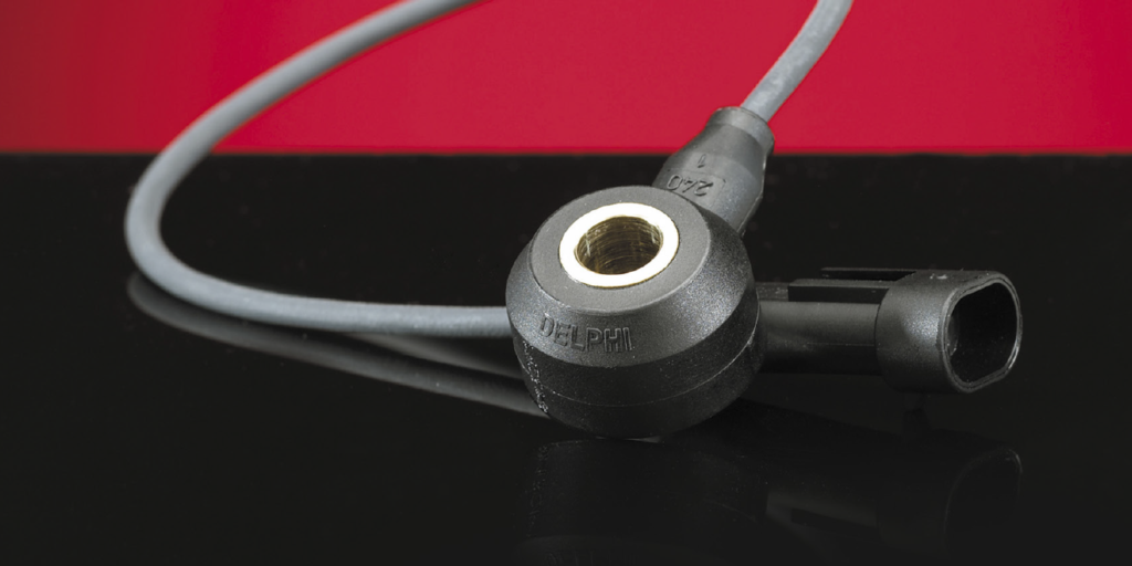
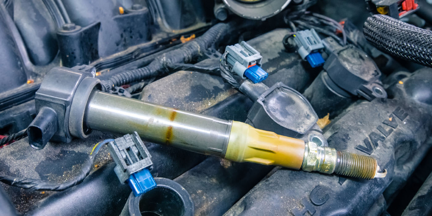
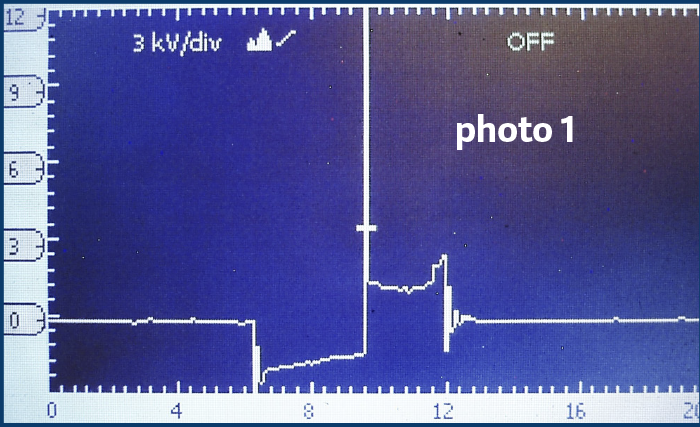
MAKING THE SPARK: An ignition coil is essentially a transformer that changes amps into volts. With the engine running, a 14.2-volt potential flows about 5.0 to 7.0 amps of current through the ignition coil primary circuit to ground. The primary circuit’s duty cycle or on/off times control the amount of “saturation” time needed to build a strong magnetic field inside the coil primary circuit (see photo 1).
Older single-coil ignitions with fixed duty cycles prevent coil overheating by using a resistor to limit primary amperage flow. Modern multi-coil systems prevent coil over-heating by electronically controlling the coil duty cycle.
The primary circuit “winding” is wrapped around a soft-iron core that creates a strong magnetic field when the primary circuit is activated. When primary current flow is interrupted by turning off the ignition module’s power diode, that magnetic field collapses into the secondary winding, which is composed of thousands of turns of very fine copper wire. Nowadays, primary voltages are typically multiplied to around 40,000 secondary volts, depending upon engine operating conditions.
As for ignition coil design, we’ve progressed from the oil-filled canister coils used through the 1970s through epoxy-filled, external-core coils of the 1980s to the waste-spark systems of the 1990s to the coil-on-plug (COP) ignitions in current use. I believe that most readers are familiar with these systems, so I’ll leave design theory to the engineers and instead focus on the real world of ignition systems diagnostics.
IONIZATION: Through ionization, an individual atom can gain a positive or negative charge by adding or subtracting electrons. When 20,000 secondary ignition volts arrive at the spark plug, the atmospheric air and gasoline compressed inside the spark plug air gap will ionize, which allows the secondary voltage to travel from the center to the ground electrode.
Spark plug voltages tend to be much higher with lean air/fuel ratios due to less ionization taking place. With a rich air/fuel ratio, spark plug voltages tend to be much lower because of better ionization. We can see that happen on an ignition scope because lean mixtures tend to drive the ignition spark line higher on the voltage scale while rich mixtures tend to drive spark lines lower.
On another note, ion-sensing ignitions have been used to time the spark according to cylinder compression. Today, the ionization effect can actually be measured by passing a low-voltage current across the spark plug gap after the combustion event. This data can then be used to augment the misfire data generated by the crankshaft position (CKP) sensor.
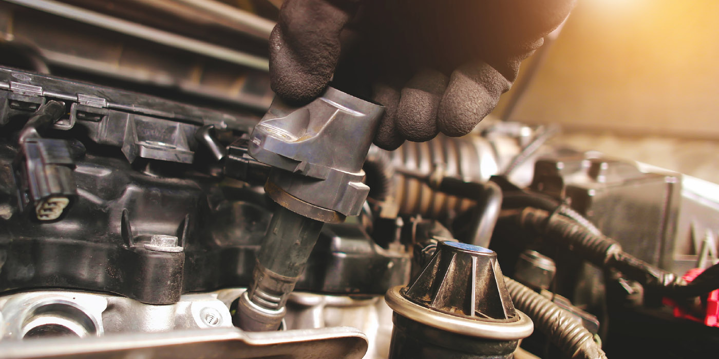
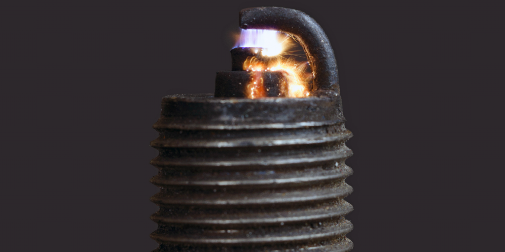
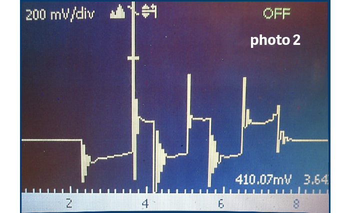
SPARK DURATION: Not to go into all of the variations of primary and secondary ignition system designs used in the past 60 years, but it’s important to note that the length of the scope’s spark line is as important as the kV of its firing spike. In conventional systems, the length of the spark line or spark duration is about 1.5 to 1.75 milliseconds (ms). Multiple-spark ignitions that fire two or three times per combustion cycle at idle are current examples of extending spark duration to reduce exhaust emissions (see photo 2).
SECONDARY VOLTAGE: Atmospheric air pressure is actually what insulates the secondary ignition. During the mid-1970s, General Motors, among others, believed that high secondary voltage combined with extra-wide, .060˝ and .080˝ spark plug gaps would reduce exhaust emissions and improve fuel economy, which it did. But, at a 12,000 feet altitude, a 54 kV potential could easily perforate a spark plug wire or distributor rotor on a brand-new vehicle. The engineering solution was to reduce the voltage potential by re-gapping the spark plugs to 040˝, which reduces the voltage potential to about 30 kV, an acceptable level in high altitude operations.
We can still see the effects of secondary perforation caused by high kV (ex. worn sparkplugs) in the familiar black carbon tracks on spark plug insulators and the tiny gray dots poking through spark plug boots and ignition coils. The lesson here is that high firing kV can cause as many problems as it solves, especially at higher altitudes.
RUNNING COMPRESSION: Since running compression on automotive engines generally increases with engine speed, a higher kV is required to fire the spark plugs and a longer duty cycle is required to saturate the coil windings.
Coil-on-plug ignitions solve that problem because a longer duty cycle can be used to fully saturate the coil primary without overheating. To reduce coil operating temperatures, the ECM varies duty cycles from very low percentages at idle or low running compressions to very high percentages at higher engine speeds and high running compressions.
SPARK TIMING AND KV: Back in the day, many veteran mechanics adjusted spark timing “by ear.” What’s really happening is that, depending upon spark plug location, the spark must occur a few degrees before top dead center (TDC) on compression stroke to allow the flame front to fully propagate across the combustion chamber. This occurs at around 12 kV. If the spark occurs too far before top-dead center (TDC), the firing kV is reduced due to the lack of compression. If the spark occurs too far past TDC, firing kV is similarly reduced due to lack of compression. The “sweet spot” occurs when the cylinder fires at idle speed at maximum kV at maximum compression.
A TECHNICAL SUMMARY: Hopefully, it’s clear that high firing kV can exist during low-throttle openings, maximum intake manifold vacuum, and lean air/fuel (a/f) mixture ratios. On the flip side, while high kV occurs at high running compressions, conventional fuel injection systems default to open-loop about a 13:1 air/fuel ratio at wide-open throttle (WOT), which reduces kV demand to the minimum needed to fire the cylinder.
Due to their unique capability of “shaping” the air/fuel charge around the spark plug air gap, gasoline direct injection (GDI) systems can enable closed-loop fuel control at WOT. In other words, GDI can inject a rich A/F ratio to form a spark “kernel” at the spark plug gap, and then abruptly shift to a lean A/F ratio to complete the “burn” in the cylinder itself. Nevertheless, while the Old School definitely meets the New School in ignition system technology, we still need to remember that the foundational aspects are still the same.
Primary Ignition Analysis: Understanding the slope
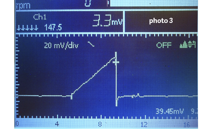
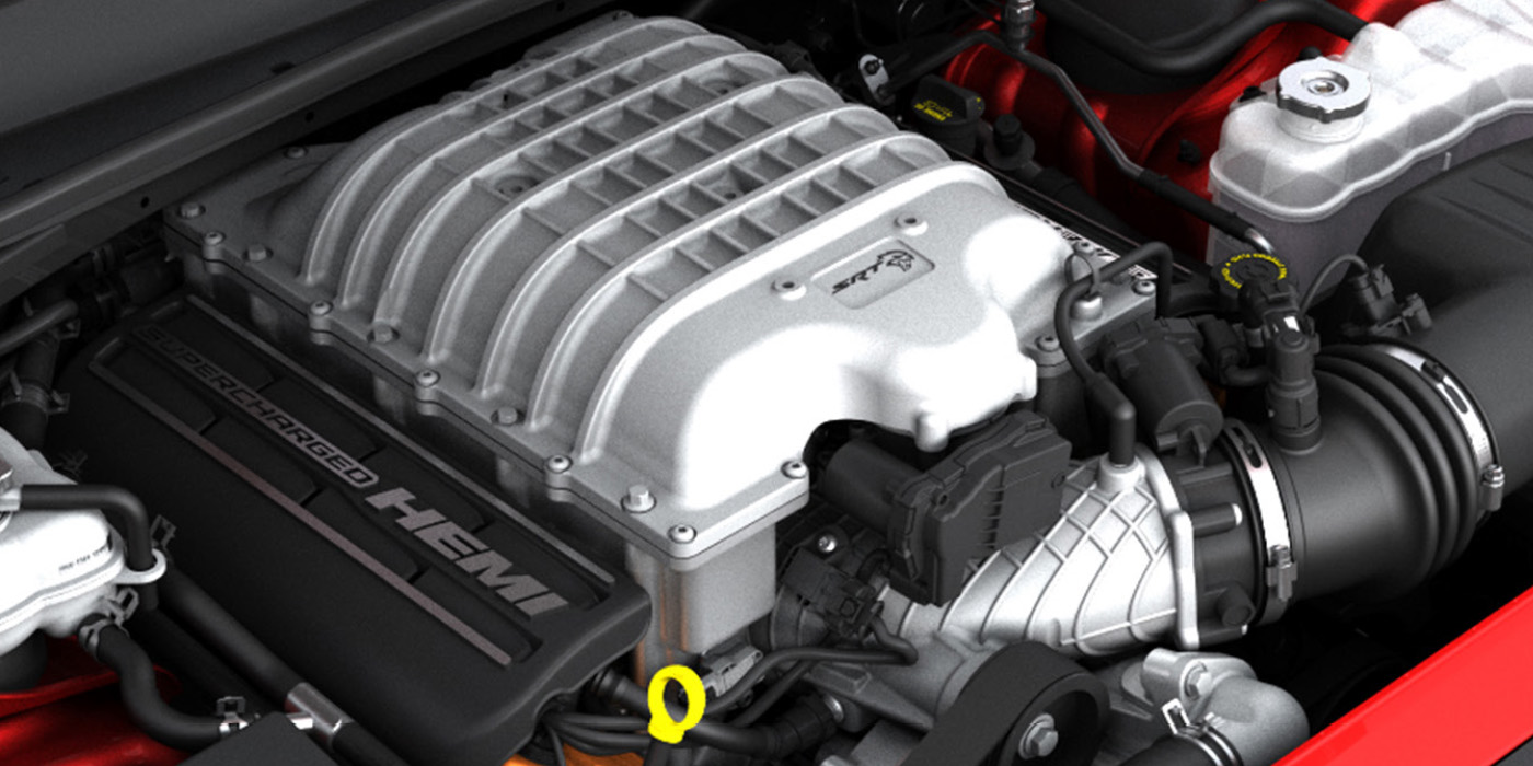
1) The most accurate method of evaluating primary circuit performance is to connect a low-amperage inductive amp to the primary B+ coil wire and observing the results on a lab scope (see photo 3).
2) This coil draws 3.3 amps, indicating that it’s used on a single-coil, low voltage system.
3) The waveform correctly ramps upward in a straight line at about 45° and terminates into a vertical drop with a small dip at the bottom before returning to zero amps.
4) Ramps curving sharply upward indicate shorted coil windings. No amperage rise indicates an open primary circuit.
5) The current rise should generally be straight-line, indicating a normal saturation rate in the coil primary circuit. The amperage rise should be in the neighborhood of three to seven amps on most coils.
6) Concerning direct primary voltage readings, always use an attenuated lead to prevent damage to your scope.
7) The primary waveform produces approximately 200 to 400 volts of induced voltage as the primary magnetic field collapses into the secondary windings.
8) The primary waveform should mirror the secondary waveform.
9) A secondary spark line sloping downward from left to right indicates high resistance in a spark plug or spark plug wire.
10) A secondary spark line sloping upward from left to right indicates a lean air/fuel mixture.
11) In general, the secondary spark line occurs at a lower kV with a rich air/fuel ratio.